Select to expand quotesaltiest1 said..

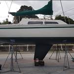
Finally brought the keel back to the 2.1metre draft it was meant to have. All lead and enjoyable to work with, cutting, planing and sanding. Last coats of primer going on now.
Crikey! that was courageous. Let us know how she sails compared to the old set up? btw Kettering has changed a bit since you were there. They're adding more pens, so the attenuator arm you were on is slowly moving seawards and the access bridge is getting moved to one of the other existing arms.
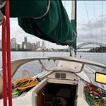
Did the last it if kiwi grip to the hatch. Looks great. installed new life lines. installed the last of the new stanchions and base plates. reinstalled the princess seat. everything went well. She is pretty much finished (on the outside)


Select to expand quote2bish said..saltiest1 said..
Finally brought the keel back to the 2.1metre draft it was meant to have. All lead and enjoyable to work with, cutting, planing and sanding. Last coats of primer going on now.
Crikey! that was courageous. Let us know how she sails compared to the old set up? btw Kettering has changed a bit since you were there. They're adding more pens, so the attenuator arm you were on is slowly moving seawards and the access bridge is getting moved to one of the other existing arms.
Sailed her down to Cronulla yesterday on a beam reach and sat very comfortably at 7 to 8 kn in 15 to 18kn if wind. Sat on 6.5 to 7.5 in 15 kn on the nose. Very happy with the result and she also now sits better at rest too. Nothing terribly noticeable about the lean under sail. She is lighter in the helm now
Select to expand quotesaltiest1 said..2bish said..saltiest1 said..
Finally brought the keel back to the 2.1metre draft it was meant to have. All lead and enjoyable to work with, cutting, planing and sanding. Last coats of primer going on now.
Crikey! that was courageous. Let us know how she sails compared to the old set up? btw Kettering has changed a bit since you were there. They're adding more pens, so the attenuator arm you were on is slowly moving seawards and the access bridge is getting moved to one of the other existing arms.
Sailed her down to Cronulla yesterday on a beam reach and sat very comfortably at 7 to 8 kn in 15 to 18kn if wind. Sat on 6.5 to 7.5 in 15 kn on the nose. Very happy with the result and she also now sits better at rest too. Nothing terribly noticeable about the lean under sail. She is lighter in the helm now
congratulations it must make you feel great to know that your plan to return the yacht to the designers inspiration was correct.A balls effort to pick up the chainsaw im sure many others would have just put up with what they had
This is interesting one to troubleshoot. I think thanks to the hero that was cutting my shore cable, I have had a few electrical issues to sort out. The last of these is the electric winch which stopped working. I have Harken 46ST as winches, with the main halyard winch as electric (lazy I know, but hauling that thing up by yourself gets old pretty quickly). It's a 2 speed, with a dual button mounted in the cockpit below the winch.
Press either button, zip squat nada, no dice. So out came the mulltimeter and into the wiring time. It turned out to be more intelligent than I thought. I was expecting two simple relays that used the cockpit buttons as control circuits for actuating the relays to allow the big fat 30amp DC power circuit to the two winch motor connections, one for the high speed and one for the low speed mode.
But nooo. Harken use a separate black box called a dual controller that houses the 30amp DC circuits and the cockpit button inputs. It acts as a safety device as well as a relay switching widget, as it provides a current overload cutoff as well as a few other simple cut off features, like pressing both buttons at once etc etc.

I tested the control circuit first. Pressing the cockpit buttons and the dual controller receives the power inputs at the correct inputs. Release the button and the power goes off. Cool. The control circuits are working.
I then tested the 30A DC circuits in and out. Power was confirmed going into the dual controller from the battery, but regardless of buttons pressed, no 30A DC power out on either of the two thick cables going to the winch motor.
Ergo, the 2 way relay in the dual controller is not switching. Problem solved! The dual controller box is not outputting DC voltage, so it needs to be repaired. I contacted Harken. Turns out they don't do repairs, you have to buy a new one. So I got a price, thinking it'd be a few hundred dollars as it is after all a simple relay device. Then I got the quotes, about $1000. Ouch.
That to me is borderline criminal for a relay with some inputs, so I'm having a go at repairing it myself. Pulling it apart, it's simply a small circuit board that sits between the relay/solenoid (dunno what you should call it) and performs the safety overrides that controls whether the relay is allowed to switch. Which is exactly the problem, something is preventing that relay from switching the 30A DC circuit to the motor.

The relay tests up fine and switches merrily every time we test, so that part is all good.The focus now is on the circuit board that controls it. I can see power getting to the board, and I can see the button inputs powering when they are supposed to, but I see no corresponding voltage output to switch the relay. (the control outputs are the blue and white wires in the picture, one is for low speed and one is for high speed.)The focus at the moment is to determine if a component on the board has failed (which looks unlikely, I can't see any signs of blown components) or whether it is an input to the board that has failed. This should be simple enough as there is no other inputs to the board except power, the buttons and the current overload sensor.
It might be as simple as the current overload circuit is toast, and it's actually doing its job. That's what the big brass angle bracket running through the current sensor on the circuit board is, it's the main 30A DC input to the relay. It's not helped by the not unexpected discovery that Harken don't even publish circuit diagrams which adds to the challenge....sigh. What ever happened to proper post sales support for expensive widgets?
So I'm trying to map out this and any other internal circuit board fail safes and test them individually till I isolate the problem.
You gotta love boats!
Select to expand quoteshaggybaxter said..
This is interesting one to troubleshoot. I think thanks to the hero that was cutting my shore cable, I have had a few electrical issues to sort out. The last of these is the electric winch which stopped working. I have Harken 46ST as winches, with the main halyard winch as electric (lazy I know, but hauling that thing up by yourself gets old pretty quickly). It's a 2 speed, with a dual button mounted in the cockpit below the winch.
Press either button, zip squat nada, no dice. So out came the mulltimeter and into the wiring time. It turned out to be more intelligent than I thought. I was expecting two simple relays that used the cockpit buttons as control circuits for actuating the relays to allow the big fat 30amp DC power circuit to the two winch motor connections, one for the high speed and one for the low speed mode.
But nooo. Harken use a separate black box called a dual controller that houses the 30amp DC circuits and the cockpit button inputs. It acts as a safety device as well as a relay switching widget, as it provides a current overload cutoff as well as a few other simple cut off features, like pressing both buttons at once etc etc.
I tested the control circuit first. Pressing the cockpit buttons and the dual controller receives the power inputs at the correct inputs. Release the button and the power goes off. Cool. The control circuits are working.
I then tested the 30A DC circuits in and out. Power was confirmed going into the dual controller from the battery, but regardless of buttons pressed, no 30A DC power out on either of the two thick cables going to the winch motor.
Ergo, the 2 way relay in the dual controller is not switching. Problem solved! The dual controller box is not outputting DC voltage, so it needs to be repaired. I contacted Harken. Turns out they don't do repairs, you have to buy a new one. So I got a price, thinking it'd be a few hundred dollars as it is after all a simple relay device. Then I got the quotes, about $1000. Ouch.
That to me is borderline criminal for a relay with some inputs, so I'm having a go at repairing it myself. Pulling it apart, it's simply a small circuit board that sits between the relay/solenoid (dunno what you should call it) and performs the safety overrides that controls whether the relay is allowed to switch. Which is exactly the problem, something is preventing that relay from switching the 30A DC circuit to the motor.
The relay tests up fine and switches merrily every time we test, so that part is all good.The focus now is on the circuit board that controls it. I can see power getting to the board, and I can see the button inputs powering when they are supposed to, but I see no corresponding voltage output to switch the relay. (the control outputs are the blue and white wires in the picture, one is for low speed and one is for high speed.)The focus at the moment is to determine if a component on the board has failed (which looks unlikely, I can't see any signs of blown components) or whether it is an input to the board that has failed. This should be simple enough as there is no other inputs to the board except power, the buttons and the current overload sensor.
It might be as simple as the current overload circuit is toast, and it's actually doing its job. That's what the big brass angle bracket running through the current sensor on the circuit board is, it's the main 30A DC input to the relay. It's not helped by the not unexpected discovery that Harken don't even publish circuit diagrams which adds to the challenge....sigh. What ever happened to proper post sales support for expensive widgets?
So I'm trying to map out this and any other internal circuit board fail safes and test them individually till I isolate the problem.
You gotta love boats!
holy **** shaggy i just get stressed because we have handed winches with ratchets in the handle and sometimes you pick up the wrong handle
way above my pay grade
Select to expand quoteboty said..
holy **** shaggy i just get stressed because we have handed winches with ratchets in the handle and sometimes you pick up the wrong handle
way above my pay grade![]()
![]()
![]()
![]()
But methinks that make you the smartest one Boty!
Select to expand quoteshaggybaxter said..
This is interesting one to troubleshoot. I think thanks to the hero that was cutting my shore cable, I have had a few electrical issues to sort out. The last of these is the electric winch which stopped working. I have Harken 46ST as winches, with the main halyard winch as electric (lazy I know, but hauling that thing up by yourself gets old pretty quickly). It's a 2 speed, with a dual button mounted in the cockpit below the winch.
Press either button, zip squat nada, no dice. So out came the mulltimeter and into the wiring time. It turned out to be more intelligent than I thought. I was expecting two simple relays that used the cockpit buttons as control circuits for actuating the relays to allow the big fat 30amp DC power circuit to the two winch motor connections, one for the high speed and one for the low speed mode.
But nooo. Harken use a separate black box called a dual controller that houses the 30amp DC circuits and the cockpit button inputs. It acts as a safety device as well as a relay switching widget, as it provides a current overload cutoff as well as a few other simple cut off features, like pressing both buttons at once etc etc.
I tested the control circuit first. Pressing the cockpit buttons and the dual controller receives the power inputs at the correct inputs. Release the button and the power goes off. Cool. The control circuits are working.
I then tested the 30A DC circuits in and out. Power was confirmed going into the dual controller from the battery, but regardless of buttons pressed, no 30A DC power out on either of the two thick cables going to the winch motor.
Ergo, the 2 way relay in the dual controller is not switching. Problem solved! The dual controller box is not outputting DC voltage, so it needs to be repaired. I contacted Harken. Turns out they don't do repairs, you have to buy a new one. So I got a price, thinking it'd be a few hundred dollars as it is after all a simple relay device. Then I got the quotes, about $1000. Ouch.
That to me is borderline criminal for a relay with some inputs, so I'm having a go at repairing it myself. Pulling it apart, it's simply a small circuit board that sits between the relay/solenoid (dunno what you should call it) and performs the safety overrides that controls whether the relay is allowed to switch. Which is exactly the problem, something is preventing that relay from switching the 30A DC circuit to the motor.
The relay tests up fine and switches merrily every time we test, so that part is all good.The focus now is on the circuit board that controls it. I can see power getting to the board, and I can see the button inputs powering when they are supposed to, but I see no corresponding voltage output to switch the relay. (the control outputs are the blue and white wires in the picture, one is for low speed and one is for high speed.)The focus at the moment is to determine if a component on the board has failed (which looks unlikely, I can't see any signs of blown components) or whether it is an input to the board that has failed. This should be simple enough as there is no other inputs to the board except power, the buttons and the current overload sensor.
It might be as simple as the current overload circuit is toast, and it's actually doing its job. That's what the big brass angle bracket running through the current sensor on the circuit board is, it's the main 30A DC input to the relay. It's not helped by the not unexpected discovery that Harken don't even publish circuit diagrams which adds to the challenge....sigh. What ever happened to proper post sales support for expensive widgets?
So I'm trying to map out this and any other internal circuit board fail safes and test them individually till I isolate the problem.
You gotta love boats!
I would throw the control box away and fit 2 interlocked solenoids. Could also fit or reconnect the thermal protection if required but if you have never tripped it to date, I would not bother with it.
Select to expand quoteshaggybaxter said..
This is interesting one to troubleshoot. I think thanks to the hero that was cutting my shore cable, I have had a few electrical issues to sort out. The last of these is the electric winch which stopped working. I have Harken 46ST as winches, with the main halyard winch as electric (lazy I know, but hauling that thing up by yourself gets old pretty quickly). It's a 2 speed, with a dual button mounted in the cockpit below the winch.
Press either button, zip squat nada, no dice. So out came the mulltimeter and into the wiring time. It turned out to be more intelligent than I thought. I was expecting two simple relays that used the cockpit buttons as control circuits for actuating the relays to allow the big fat 30amp DC power circuit to the two winch motor connections, one for the high speed and one for the low speed mode.
But nooo. Harken use a separate black box called a dual controller that houses the 30amp DC circuits and the cockpit button inputs. It acts as a safety device as well as a relay switching widget, as it provides a current overload cutoff as well as a few other simple cut off features, like pressing both buttons at once etc etc.
I tested the control circuit first. Pressing the cockpit buttons and the dual controller receives the power inputs at the correct inputs. Release the button and the power goes off. Cool. The control circuits are working.
I then tested the 30A DC circuits in and out. Power was confirmed going into the dual controller from the battery, but regardless of buttons pressed, no 30A DC power out on either of the two thick cables going to the winch motor.
Ergo, the 2 way relay in the dual controller is not switching. Problem solved! The dual controller box is not outputting DC voltage, so it needs to be repaired. I contacted Harken. Turns out they don't do repairs, you have to buy a new one. So I got a price, thinking it'd be a few hundred dollars as it is after all a simple relay device. Then I got the quotes, about $1000. Ouch.
That to me is borderline criminal for a relay with some inputs, so I'm having a go at repairing it myself. Pulling it apart, it's simply a small circuit board that sits between the relay/solenoid (dunno what you should call it) and performs the safety overrides that controls whether the relay is allowed to switch. Which is exactly the problem, something is preventing that relay from switching the 30A DC circuit to the motor.
The relay tests up fine and switches merrily every time we test, so that part is all good.The focus now is on the circuit board that controls it. I can see power getting to the board, and I can see the button inputs powering when they are supposed to, but I see no corresponding voltage output to switch the relay. (the control outputs are the blue and white wires in the picture, one is for low speed and one is for high speed.)The focus at the moment is to determine if a component on the board has failed (which looks unlikely, I can't see any signs of blown components) or whether it is an input to the board that has failed. This should be simple enough as there is no other inputs to the board except power, the buttons and the current overload sensor.
It might be as simple as the current overload circuit is toast, and it's actually doing its job. That's what the big brass angle bracket running through the current sensor on the circuit board is, it's the main 30A DC input to the relay. It's not helped by the not unexpected discovery that Harken don't even publish circuit diagrams which adds to the challenge....sigh. What ever happened to proper post sales support for expensive widgets?
So I'm trying to map out this and any other internal circuit board fail safes and test them individually till I isolate the problem.
You gotta love boats!
www.ebay.co.uk/itm/HARKEN-ELECTRIC-WINCH-DUEL-FUNCTION-CONTROL-BOX-DF-40-12HL/153972777725?hash=item23d97e22fd:g:~tMAAOSwsqxcKlg-
Not sure if it's exactly the right one. Will the guy post it to OZ for you?
Select to expand quotetarquin1 said..shaggybaxter said..
This is interesting one to troubleshoot. I think thanks to the hero that was cutting my shore cable, I have had a few electrical issues to sort out. The last of these is the electric winch which stopped working. I have Harken 46ST as winches, with the main halyard winch as electric (lazy I know, but hauling that thing up by yourself gets old pretty quickly). It's a 2 speed, with a dual button mounted in the cockpit below the winch.
Press either button, zip squat nada, no dice. So out came the mulltimeter and into the wiring time. It turned out to be more intelligent than I thought. I was expecting two simple relays that used the cockpit buttons as control circuits for actuating the relays to allow the big fat 30amp DC power circuit to the two winch motor connections, one for the high speed and one for the low speed mode.
But nooo. Harken use a separate black box called a dual controller that houses the 30amp DC circuits and the cockpit button inputs. It acts as a safety device as well as a relay switching widget, as it provides a current overload cutoff as well as a few other simple cut off features, like pressing both buttons at once etc etc.
I tested the control circuit first. Pressing the cockpit buttons and the dual controller receives the power inputs at the correct inputs. Release the button and the power goes off. Cool. The control circuits are working.
I then tested the 30A DC circuits in and out. Power was confirmed going into the dual controller from the battery, but regardless of buttons pressed, no 30A DC power out on either of the two thick cables going to the winch motor.
Ergo, the 2 way relay in the dual controller is not switching. Problem solved! The dual controller box is not outputting DC voltage, so it needs to be repaired. I contacted Harken. Turns out they don't do repairs, you have to buy a new one. So I got a price, thinking it'd be a few hundred dollars as it is after all a simple relay device. Then I got the quotes, about $1000. Ouch.
That to me is borderline criminal for a relay with some inputs, so I'm having a go at repairing it myself. Pulling it apart, it's simply a small circuit board that sits between the relay/solenoid (dunno what you should call it) and performs the safety overrides that controls whether the relay is allowed to switch. Which is exactly the problem, something is preventing that relay from switching the 30A DC circuit to the motor.
The relay tests up fine and switches merrily every time we test, so that part is all good.The focus now is on the circuit board that controls it. I can see power getting to the board, and I can see the button inputs powering when they are supposed to, but I see no corresponding voltage output to switch the relay. (the control outputs are the blue and white wires in the picture, one is for low speed and one is for high speed.)The focus at the moment is to determine if a component on the board has failed (which looks unlikely, I can't see any signs of blown components) or whether it is an input to the board that has failed. This should be simple enough as there is no other inputs to the board except power, the buttons and the current overload sensor.
It might be as simple as the current overload circuit is toast, and it's actually doing its job. That's what the big brass angle bracket running through the current sensor on the circuit board is, it's the main 30A DC input to the relay. It's not helped by the not unexpected discovery that Harken don't even publish circuit diagrams which adds to the challenge....sigh. What ever happened to proper post sales support for expensive widgets?
So I'm trying to map out this and any other internal circuit board fail safes and test them individually till I isolate the problem.
You gotta love boats!
www.ebay.co.uk/itm/HARKEN-ELECTRIC-WINCH-DUEL-FUNCTION-CONTROL-BOX-DF-40-12HL/153972777725?hash=item23d97e22fd:g:~tMAAOSwsqxcKlg-
Not sure if it's exactly the right one. Will the guy post it to OZ for you?
G'day Tarquin,
that's an awesome price! Yes, they are different, talking with Harken they are programmed to match the size and load rating of the winch and my serial numbers differ quite a bit from this one.
Bugger, that would have been a hell of a boon if it matched, thanks very much!
Select to expand quoteJode5 said..
I would throw the control box away and fit 2 interlocked solenoids. Could also fit or reconnect the thermal protection if required but if you have never tripped it to date, I would not bother with it.
G'day Jode,
That's really interesting, I haven't come across interlocked solenoids before. If I understand this correctly, an interlocked solenoid has a fail safe where de-energising a circuit allows another circuit to energise, is that right?
So am I right in thinking you would have the low speed control circuit (when you press the low speed button) fed to the second solenoid as the required fail safe before the high speed circuit (press high speed button) can operate? And vice versa?
Please excuse my ignorance, but this is fascinating. I'm showing my inner geek here ![]() .
.
Thanks very much!
A couple simple questions shaggy
Do you have a control circuit line that goes from the black box to your switch panel at the nav station?
Not in the drawing and I would expect that you could switch on/off at you panel.
I take it your speed controller is just two buttons, one fast and one slow.
It is not infinitely controllable ( ie. push one for slow. twice for faster, three times and so on.)
Finally, there is no reverse function is there?
I am thinking along the same line as jode.
gary
Select to expand quotegarymalmgren said..
A couple simple questions shaggy
Do you have a control circuit line that goes from the black box to your switch panel at the nav station?
Not in the drawing and I would expect that you could switch on/off at you panel.
I take it your speed controller is just two buttons, one fast and one slow.
It is not infinitely controllable ( ie. push one for slow. twice for faster, three times and so on.)
Finally, there is no reverse function is there?
I am thinking along the same line as jode.
gary
G'day Gary,
Do you have a control circuit line that goes from the black box to your switch panel at the nav station?
Yes, just not at the Nav station. I have a separate panel in the rear starboard berth with an on/off rocker to power the control circuits.
There is a 80A circuit breaker for the main DC bus voltage to the solenoid that is on all the time. (sorry I said 30A in the earlier post, its actually an 80A circuit.)
I take it your speed controller is just two buttons, one fast and one slow.
Yes, it uses separate ring gears on the winch to change the speed (two big fat DC cables to the winch), so the two controls circuits are identical for all intents. Same buttons, same voltage and current, for the 80A main feed the solenoid has two outputs from a single input, so control circuit A switches the solenoid to output A, control circuit B switches the solenoid to output B.
It is not infinitely controllable ( ie. push one for slow. twice for faster, three times and so on.)
No, the buttons are a simple push and hold. Take your finger off the button and the power is cut. If you push the button more than once there is no change, just 12v on or off.
Edit: I didn't mention it prior as to not confuse the explanation, but the buttons are actually digital not analogue, so they have a small decoder between them and the dual controller to convert the ones and zeros to a simple voltage on/voltage off. So they are in principle a simple analogue output, push to transmit a 12v supply, and release to cut off the 12V supply.
Cheers!
SB
Not much help but last year I was asked to go sailing with a friend of a friend. He wanted to do a transatlantic crossing and wanted some advice/help setting up the boat. A Dufour something. I suggested he needed electric winches as there were only 2 manual ones in the cockpit. He wanted to cross with just him and his girlfriend. She couldn't winch the genoa in let alone furl it by herself. To cut the story short even to convert the Harken winches to electric was going to costs about 5000 euros,plus another winch for the mainsheet. There was 1 in the companion way,not much good at 0200 when you are on watch by yourself and get hit by a squall. Anyhow I was amazed how expensive Harken winches are.
I was also amazed how badly the boat was set up. It would have cost over 20000 euros. Safety equipment,new lines,some basic training for them etc.
Basically Harken equipment is great but expensive.
Select to expand quoteshaggybaxter said..
This is interesting one to troubleshoot. I think thanks to the hero that was cutting my shore cable, I have had a few electrical issues to sort out. The last of these is the electric winch which stopped working. I have Harken 46ST as winches, with the main halyard winch as electric (lazy I know, but hauling that thing up by yourself gets old pretty quickly). It's a 2 speed, with a dual button mounted in the cockpit below the winch.
Press either button, zip squat nada, no dice. So out came the mulltimeter and into the wiring time. It turned out to be more intelligent than I thought. I was expecting two simple relays that used the cockpit buttons as control circuits for actuating the relays to allow the big fat 30amp DC power circuit to the two winch motor connections, one for the high speed and one for the low speed mode.
But nooo. Harken use a separate black box called a dual controller that houses the 30amp DC circuits and the cockpit button inputs. It acts as a safety device as well as a relay switching widget, as it provides a current overload cutoff as well as a few other simple cut off features, like pressing both buttons at once etc etc.
I tested the control circuit first. Pressing the cockpit buttons and the dual controller receives the power inputs at the correct inputs. Release the button and the power goes off. Cool. The control circuits are working.
I then tested the 30A DC circuits in and out. Power was confirmed going into the dual controller from the battery, but regardless of buttons pressed, no 30A DC power out on either of the two thick cables going to the winch motor.
Ergo, the 2 way relay in the dual controller is not switching. Problem solved! The dual controller box is not outputting DC voltage, so it needs to be repaired. I contacted Harken. Turns out they don't do repairs, you have to buy a new one. So I got a price, thinking it'd be a few hundred dollars as it is after all a simple relay device. Then I got the quotes, about $1000. Ouch.
That to me is borderline criminal for a relay with some inputs, so I'm having a go at repairing it myself. Pulling it apart, it's simply a small circuit board that sits between the relay/solenoid (dunno what you should call it) and performs the safety overrides that controls whether the relay is allowed to switch. Which is exactly the problem, something is preventing that relay from switching the 30A DC circuit to the motor.
The relay tests up fine and switches merrily every time we test, so that part is all good.The focus now is on the circuit board that controls it. I can see power getting to the board, and I can see the button inputs powering when they are supposed to, but I see no corresponding voltage output to switch the relay. (the control outputs are the blue and white wires in the picture, one is for low speed and one is for high speed.)The focus at the moment is to determine if a component on the board has failed (which looks unlikely, I can't see any signs of blown components) or whether it is an input to the board that has failed. This should be simple enough as there is no other inputs to the board except power, the buttons and the current overload sensor.
It might be as simple as the current overload circuit is toast, and it's actually doing its job. That's what the big brass angle bracket running through the current sensor on the circuit board is, it's the main 30A DC input to the relay. It's not helped by the not unexpected discovery that Harken don't even publish circuit diagrams which adds to the challenge....sigh. What ever happened to proper post sales support for expensive widgets?
So I'm trying to map out this and any other internal circuit board fail safes and test them individually till I isolate the problem.
You gotta love boats!
Are you testing the relay operation for "clicking" in the condition shown in the photo? Ie no heavy current connection to the relay?
When a button is pressed do you get any voltage on the "button 1" and "button 2" outputs that you have labelled above. I suspect not.
Can you confirm that the labelled earth wire goes to the relay as well. Ie if it does then that is the ground for the "button 1" and "button 2" output connections to separate control coils in the relay. If it does not connect to the relay then things are more complicated. I will not go down that rabbit hole yet.
All this is leading up to bypassing the controller - a auto reset circuit breaker for overload protection, and direct wire the buttons to control the larger changeover relay. It is how the changeover relay is controlled that I am not certain of.
the buttons are actually digital not analogue, so they have a small decoder between them and the dual controller to convert the ones and zeros to a simple voltage on/voltage off.
Shaggy. I have to admit that when I read this my eyes clouded over.
I think you just might have a system that is too smart for its own boots.
gary
Select to expand quotegarymalmgren said..
the buttons are actually digital not analogue, so they have a small decoder between them and the dual controller to convert the ones and zeros to a simple voltage on/voltage off.
Shaggy. I have to admit that when I read this my eyes clouded over.
I think you just might have a system that is too smart for its own boots.
gary
Yeah, I often wonder that too ![]() . The idea of the digital system is you can daisy chain multiple buttons together in series.
. The idea of the digital system is you can daisy chain multiple buttons together in series.
God knows how big a yacht they think we install this stuff into, maybe some people need an electric winch button in the galley or something??
maybe some people need an electric winch button in the galley or something
After all these years it was staring me in the face.
A button for an electric winch would fill the little space between the two galley lockers perfectly.
Why on earth didn't I think of that before?
Thanks for waking me up. Shaggy.
(0f course I can only afford the button)
Select to expand quotegarymalmgren said..
maybe some people need an electric winch button in the galley or something
After all these years it was staring me in the face.
A button for an electric winch would fill the little space between the two galley lockers perfectly.
Why on earth didn't I think of that before?
Thanks for waking me up. Shaggy.
(0f course I can only afford the button)
Now if we could just make that galley button depower the main and jib sheets we'd be millionaires !
Select to expand quoteshaggybaxter said..Jode5 said..
I would throw the control box away and fit 2 interlocked solenoids. Could also fit or reconnect the thermal protection if required but if you have never tripped it to date, I would not bother with it.
G'day Jode,
That's really interesting, I haven't come across interlocked solenoids before. If I understand this correctly, an interlocked solenoid has a fail safe where de-energising a circuit allows another circuit to energise, is that right?
So am I right in thinking you would have the low speed control circuit (when you press the low speed button) fed to the second solenoid as the required fail safe before the high speed circuit (press high speed button) can operate? And vice versa?
Please excuse my ignorance, but this is fascinating. I'm showing my inner geek here ![]() .
.
Thanks very much!
Hi Shaggy
You electrically interlock the solenoids with two relays.
Not much happening on this forum anymore. Anyway Icon has her new pinstripe and name complete. Ready for Australian rego paper work and the O.N number is getting looked into for below. Should be in tassie Christmas if all goes well.

The previous owner of my trailer sailer upgraded the motor from a Mercury 8hp 2 stroke to a Honda 10hp 4 Stroke. As a bonus it has electric start. But the mounting bracket on the stern is not happy with the weight change and has split the top bar at the top bolt hole.
So, with the help of a neighbour, I built an A frame to remove the motor from the bracket. They weigh a bit over 35kgs, so it is not something you want to drop on your toes.
A trailer manufacturer up the road is welding in some reinforcing, so should be back on the water next week.

Select to expand quotesouthace said..
Not much happening on this forum anymore. Anyway Icon has her new pinstripe and name complete. Ready for Australian rego paper work and the O.N number is getting looked into for below. Should be in tassie Christmas if all goes well.
You do know that Tasssie is still part of Australia & you don't need Australian rego to go there!!! ![]()
Lookin good mate :)
Select to expand quoteLazzz said..southace said..
Not much happening on this forum anymore. Anyway Icon has her new pinstripe and name complete. Ready for Australian rego paper work and the O.N number is getting looked into for below. Should be in tassie Christmas if all goes well.
You do know that Tasssie is still part of Australia & you don't need Australian rego to go there!!! ![]()
Lookin good mate :)
It's just a nice stop off, I love tassie Christmas time until march then I will head north then east.
Bit the bullet today and started a job I've been putting off for a while. The glazing rubber was perished and not doing its job.
Window out and off to Grippy Rubber at Kings Park
The guys there are very helpful and patient and found the right glazing wedge.
Old glazing wedge removed and cleaned out the alloy frame. The glass is still bonded securely into the frame so left it alone. New glazing wedge goes in easy with warm soapy water and a flyscreen roller helps.
The back of the frame cleaned up with a scotchbrite disc in the grinder.
Cabin side masked up and window replaced using roof and gutter silicone. Much better and less messy than Sikaflex for this job.
Two done two to go. Shouldn't have put it off this long, finding the right glazing wedge and fitting it was alot easier than I thought it would be.


Good one, the dyneema looks great. Do the lines sag much when you open the boarding gates?
Select to expand quotetroubadour said..
Bit the bullet today and started a job I've been putting off for a while. The glazing rubber was perished and not doing its job.
Window out and off to Grippy Rubber at Kings Park
The guys there are very helpful and patient and found the right glazing wedge.
Old glazing wedge removed and cleaned out the alloy frame. The glass is still bonded securely into the frame so left it alone. New glazing wedge goes in easy with warm soapy water and a flyscreen roller helps.
The back of the frame cleaned up with a scotchbrite disc in the grinder.
Cabin side masked up and window replaced using roof and gutter silicone. Much better and less messy than Sikaflex for this job.
Two done two to go. Shouldn't have put it off this long, finding the right glazing wedge and fitting it was alot easier than I thought it would be.
Nice one! it's great when a boat job takes less time than you imagine!
Select to expand quote2bish said..
Good one, the dyneema looks great. Do the lines sag much when you open the boarding gates?
No mate the forward and aft lines are independent and lashed forward and aft.
Select to expand quotetroubadour said..
Bit the bullet today and started a job I've been putting off for a while. The glazing rubber was perished and not doing its job.
Window out and off to Grippy Rubber at Kings Park
The guys there are very helpful and patient and found the right glazing wedge.
Old glazing wedge removed and cleaned out the alloy frame. The glass is still bonded securely into the frame so left it alone. New glazing wedge goes in easy with warm soapy water and a flyscreen roller helps.
The back of the frame cleaned up with a scotchbrite disc in the grinder.
Cabin side masked up and window replaced using roof and gutter silicone. Much better and less messy than Sikaflex for this job.
Two done two to go. Shouldn't have put it off this long, finding the right glazing wedge and fitting it was alot easier than I thought it would be.
Looks great! Ya gotta be happy with them![]()