Select to expand quoteWindxtasy said..Flex2 said..
Nice one Freezer. Your unit looks good. I was starting a similar design for shoulder/helmet mounting that has similar angle (toying with the idea of making the angle adjustable for different sized arms and helmet). I ordered some bits and whilst waiting for them to arrive came across another variable (discovered whilst talking Windxtasy through her build). That is the polarity of the wireless charge receivers.
This is important if you try and design something both slimline and easy to build (the wireless charge soldering is probably the hardest connection to make which might put some off) so using the plug and play USB connection is much easier...the USB's come in two orientations so need to know which one to get.
I have two types of receiver and two types of charge mat. All only work one way. i.e. first photo (electronics up) works, but second photo (electronics down) doesn't. So for me its important to load the correct way when assembling the unit. However, Windxtasy's receivers work both ways on the charge mat. Verified by measuring 5V and the charge mat indicator. She bought from the same supplier I suggested so I can only think her charge mat is superior to mine. My phone only charges one way (screen up). Our charge mats are all 10W.
This might be an issue for those lucky enough that it works both ways so they assemble unit one way. However if they then use a different charge mat (old one fails etc) they might find the unit doesn't charge. For this reason it seems better to assemble so they are oriented as per first photo. I could not find any reference to polarity of receiver or transmitter in the Qi standard but I didn't look very hard and thought I'd ask here.
Anyone know if Windxtasy coil/mat combo are a fluke? Or, what to look for in a charge mat that works both ways?
PS Not sure what you are refraining to with Jan's software only being for one type of sailor. You get nice realtime stats whilst sailing (changeable/selectable whilst sailing and not stopping) and 4 screens of stats when you stop/crash. Now an additional/resettable 2 stats screens of last 5 runs with the addition of second button/reed switch. So seems plenty of data for both types of sailor (although I'm nagging Jan to add some more realtime stats).


My wireless coil has a much smaller PCB than yours, looks about 1/3rd the size, so it is obviously a different model.
can't take a photo because it is at home. It works both ways but I have orientated it like your first pic because it fits in the box with the better that way
its non-polarised so shouldn't matter which way the coil goes. If it matters, something else is happening- like the solid copper ground plane of the PCB is creating a "shorted turn" and stopping the charge pad from operating. If you fold the PCB up 90 degrees I bet it works. Or fold the PCB over the coil with ferrite tape between coil and PCB.
Its important to use ferrite tape if you have a PCB behind the coil.
Until now I have been charging through USB only, mainly though the PC since I was constantly trying changes to the software.
I bought 2 types of usb connectors on my qi receivers. Type A is the correct one, where the cable goes to the back side of the T5. The type B goes to the display an needs correction. It comes in a flexible protective cover, but you can peel it off nicely and get to the bare components. The ferrite tape is causing it either to shield it from charging or enhances it. As mentioned in the instructions of Jan you can use the ferrite tape to stick it to your case.
Since I have also a wrong type B connector, I soldered 2 wires directly on the (flexible) pcb, since it came with 2 extra pads so I can leave the USB connector in tackt for now. Measuring the voltage over the wire it was a whopping 7V and looked a bit steep for me. This was however without any load, not connected to the T5 board. Next thing is soldering the wires to the charge controler pin and gnd of the T5 board. Hopefully it is within specs and don't blow-up anything...


I had send a email to Good-display (manufacturer of the e-paper) about this issue, and I got a direct reply where they indeed confirm that the controller is photo-sensitive. More important, the e-paper itselfs is also degrading under uv light ! So, just keep in mind that direct sunlight is not so good for the e-paper. Maybe some kind of UV-protection would be nice. They are also working on this subject.
Greetings, Jan.

Select to expand quoterp6conrad said..
I had send a email to Good-display (manufacturer of the e-paper) about this issue, and I got a direct reply where they indeed confirm that the controller is photo-sensitive. More important, the e-paper itselfs is also degrading under uv light ! So, just keep in mind that direct sunlight is not so good for the e-paper. Maybe some kind of UV-protection would be nice. They are also working on this subject.
Greetings, Jan.
we'll just cover the screen with sunscreen when we do ourselves :)
More seriously though, Flex has used a polycarbonate face on his UV printed boxes, and fortuitously, Polycarbonate as a material blocks almost the entire relevant UV spectrum, meaning both UVA and UVB. The material absorbs UV radiation and does not allow it to be transmitted through.
It has 10 times more impact resistance than plastic and glass.
The disadvantage of Polycarbonate is that it has weak scratch resistance because its a soft material. You can have a scratch resistant coating put over the Polycarbonate which will keep all its properties and add scratch resistance.
We might need to take our polycarbonate faceplates along to a lens coater and have them coated with a scratch resistant coating...
I wouldn't worry too much about the UV damaging the screen. Just don't leave it in the sun when you aren't using it and it will probably last for 10 years.
Cover up the chip with tape (aluminium foil tape is pretty good) and go sailing.
No need to add a non scratch coating. Can purchase scratch resistant Polycarbonate (Lexan MR10 and Makrolon AR2 I think). I was actually using this for all my prototypes in the beginning. It works well as I purchased some for another project that has been seriously abused for 8+ years now and holding up well. I ran out of offcuts so scrounged a free sheet of standard polycarbonate. Despite my current unit being heavily scratched this has come with heavy use and you don't notice on the water.
There should be piles of offcuts of the abrasion resistant stuff around as most of the Covid shields used at over the counter sales are probably made of the stuff. Will start scrounging for some.
I went the cheap and cheerful clear lid.
Pulled apart some old computer screens, they have some nice 2.5mm hard plastic in there which appears to be fairly abrasion resistant.
What about buying some clearance phone protector non-glass) and cutting to size? I had one on a GW60 and it did the job.
Another finding about the "dynamic model" from the ublox M8N : The default dynamic model is "PORTABLE". There is also a model "SEA" available. This model can be set in the "config.txt", but there are imporatant disadvantages :
-Max speed is limited to ca 25 m/s, if you are faster, the reported doppler speeds drops to ZERO.
-Max height over sea-level is limited, if you are too high, the GPS want get a fix. Found this out while I was on a skitrip, ca 1000 - 2300 m above sea-level.
-Even if you have a fix, and good reception, but you are ascending, the gps will loss the fix and report 0 sats. Noticed this on a car-test, where the gps losses all sats on the exact same point in the traject.
So, I see no advantages of using the "SEA" model anymore ! The hope was that it could be more precise for speed-surfing, but this could not be seen in the measurements.
Some info about this dynamic model :
wiki.paparazziuav.org/wiki/Module/GPS_UBlox_UCenter
I came to the same conclusion, I'm not worried about the height cut out, but the speed cut out is the killer.
Sorry can't remember what I settled on, "portable" does ring a bell though.
I remember that Tom Chalko experimented with what he called '2D sea level fix' setting in the GT-11 and/or GT31 SIRF chipsets. His reasoning was that better accuracy should be able to be obtained by fixing the assumed altitude to sea level. I have a felling that this applied to the positional rather than the Doppler, and when we went to Doppler he may have saw it as not relevant. In any case, it was abandoned. Next time I see him I will try to remember to ask him about it.
But it seems that the 'Portable' setting seems to be the most appropriate for us, although it would be interesting to know how the data from the 'pedestrian' and 'Airborne1G' would differ.
I fully understand why fixing 1 variable like height to all the unknowns would lead to better accuracy of position. I never knew however that's why they had a land and sea setting... I'm not sure if this is also true for doppler speed. If anyone can explain this to me it would be appreciated.
I looked into adding a shield beneath the gps antenna to improve the signal. When I looked into the size, the recommendedradius should be at least a quarter of the wavelength of the radio waves the antenna, to enhance the signal on the antenna side by reflection.
To block possible signals that are reflected from the water, I expect it's
just line of sight. The larger the shield, the more it is blocking signals coming from behind. I think this is the main concern for us right? So anything that extends the PCB of the BN2xx would help, preferably several times larger than the height. 1-2cm could already be significant. I bought some copper-conducting tape do do some experiments. It will probably only work/improve if the gps is horizontal to the water.
Last thing I'm struggling with are the maximum allowed acceleration criteria that remains the same. I think there is a dependency to the sample frequency. I have read in this thread that some people believe it is the chop related. But then it should be gone when traveling by car right? And it doesn't...
Having longer integration time on some measurements does increase the accuracy of the measurements, but only to a certain point. Having higher sample rates increases the amount of samples and therefore also reduces error. However the maximum acceleration is per measured point and not per distance or avg... That's why I believe we can't make use of the benefits of higher sample rates (>5Hz). I have seen individual points in GPSresult that exceeded the max of 5m/s2 allowed for a 10Hz sample. Going back to 5Hz solves it, but I'm not convinced it is less accurate. Yes, the max speed on individual sample should not be used but a 1s or 2s would still be pretty good. Perhaps some equations could prove my theory or what I see happening (1Hz =>5m/s2; 10Hz=>5?SQRT(10)m/s2). But for now the restrictions on 5m/s2 per sample does not sound realistic for higher sample rates and forces me to go back to 5Hz. Wonder how the 25Hz devices are performing on this.
Select to expand quoteFreezer said..
Last thing I'm struggling with are the maximum allowed acceleration criteria that remains the same. I think there is a dependency to the sample frequency. I have read in this thread that some people believe it is the chop related. But then it should be gone when traveling by car right? And it doesn't...
In the attached screenschot, you see the speedpoints of 4 esp-gps, 2 were fixed on the boom, two were on my helmet. You see a rather good correlation to the blue en red plot (boom gps), and I assume that this is the "chop" effect.
The other 2 curves (green, orange) are from my helmet, these show less "noise", but again a nice correlation. It looks that they are in "anti-phase" with the red and blue, which makes sense : the body and head are in antiphase with the movements of the board, as you bend your knees with every wave. So, the "noise" is not completely random, but somehow correlated to the "vertical" movements.
I am convinced that the position on the helmet is superior for the reception, and for the least acceleration noise.
Greetings, Jan.

Thanks Jan, so you do see the chop visible in the data between the mounts on the boom vs. helmet. That means the data is more accurate than I thought and makes the need for the maximum acceleration (per data point) need to be increased for units with higher sample rate. Alternatively it could still use an average over 1 second max acceleration equal to the current 5m/s2 and not simply filter-out the higher readings. It's not noise nor invalid. I have seen 10Hz runs being labeled as invalid by gps-speedsurfing, where it shouldn't.
Select to expand quoteFreezer said..
Thanks Jan, so you do see the chop visible in the data between the mounts on the boom vs. helmet. That means the data is more accurate than I thought and makes the need for the maximum acceleration (per data point) need to be increased for units with higher sample rate. Alternatively it could still use an average over 1 second max acceleration equal to the current 5m/s2 and not simply filter-out the higher readings. It's not noise nor invalid. I have seen 10Hz runs being labeled as invalid by gps-speedsurfing, where it shouldn't.
Yep using a 1s average for acceleration makes a lot of sense.
For the technical stuff I don't think you can go past boardsurfre.
his GPSSpeadreader uses these acceleration figures,
1hz, 4
5hz, 8
10hz, 16
The saw tooth wave form is a puzzle. I don't think you can put it down to any one thing. Some of it is definitely real. But some of it could be noise.
I think gps- speedsurfing is mainly aimed at 1hz devices

So this is a 10hz stationery test, sitting rock steady on an outside table. This has to be noise. I think just atmospheric fluctuations could do this
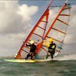
This video (start at 2min) is a good example of how much a device shakes even at Luderitz:
rp6conrad (and contributors?), I'd encourage you to clarify ownership and licensing of your work, especially pertaining to commercial use.
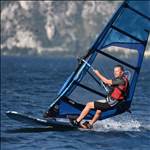
The Motion on Bjorn's arm is a bit too loose. In my experience, if it's just done up a little firmer, it does not shake around as much as that, and does not slip around the arm. But I don't wear a slippery rashie over my wetsuit either. ![]()
Select to expand quoteJulienLe said..
rp6conrad (and contributors?), I'd encourage you to clarify ownership and licensing of your work, especially pertaining to commercial use.
Jan certainly has put the most effort in so really its his call. My effort (3d print) any 16 year old can probably wip up in 20 mins (took me a bit longer though). I've shared my design pretty much open source, use it how ever you want. Would be nice to get credit but who cares.
In addition to whatever licensing I have suggested at the very least Jan add a way for to donate. Jan could also charge for his software and could ensure no pirating by giving users 'free' use for 2 months or so after which the software locks up and a unique code is required requiring some form of payment. (like GPS action replay as example). This would help fund/motivate Jan to keep development of his software going (I've told him lots of crazy potential ideas). Currently we are at around maybe 5/6 users???
Quite a number of sailors have asked me if I would make some units for them when they have seen it. I'm trying to resist going down that way firstly because I have better things to do. Secondly, even making a couple of units would lead to others wanting more and I'd end up as JulienLe...most here probably don't want to create the headache you (Julien) has. Building them is one thing but support, warranty etc...damm nightmare.. I've been in the service industry 30 years dealing with 'customers' and had enough of all that.
Its not like one is going to get rich building these things...its a fairly small and fussy customer base. (I'm guessing Julien doesn't drive around in a Ferrari) If someone does take it on then great, but you would need to charge at least pretty much the same as another device to stay afloat long term.
Personally I think its better off just fully open source (Jan charge some sort of nominal fee for his software or at least let us donate) so there is an other 'option' out there for those that want to put the effort in. I'm sure Windxtasy and Elmo will agree its a good feeling building your own device and they may have learnt something on the way.
My current 'plan' in long list of stuff, is build a few more extra units (as loaners) and maybe make a video tutorial on building/programming to show a) how easy it is and b) get newbies not familiar with Arduino over a few stumbling blocks (have helped two so far) and the same basic issues arise.
I am hoping the brains trust and especially any materials engineering experts out there might be able to help me with finishing the box for my ESP32 GPS.
There hasn't been any wind lately so what do windsurfers do when there is no wind? They make GPS units to measure their speeds when there is wind.
I have reported on my adventures in building the GPS earlier.
Flex has reported on his adventures with his 3D printed boxes, which was very educational. I have had quite a rollercoaster of experiences with mine also, and will document them here so you will not make the same mistakes.
Flex 3D printed some boxes for me.
He told me that when filling his units with potting epoxy the epoxy leaked out through the very porous 3D print, so I decided to seal my boxes with some Botecote epoxy that I had. I painted both the inside and outside of the boxes. First mistake - Flex has so accurately designed his 3 D prints that there very little tolerance, and the epoxy coating prevented me being able to insert the GPS module into the recess. I had to dremel away some of the epoxy to fit the GPS module in, and also to keep the switch recess clear.
lesson 1: only seal the outside of the box, not the inside.
lesson 2. The epoxy does not like to coat the 3D print in a thin layer - it beads up. It has a minimum meniscus thickness, like molten glass, so if you want a smooth finish you have to keep topping up the dry spots until the epoxy remains uniform.
The epoxy coating did stop the potting epoxy from leaking out, so a win there.
I decided that a surround for the screen would make for a more professional looking result, and serendipitously discovered that the black surround prevents ghosting of the screen in bright sunlight. The surround I cut from a folder cover is only about a half mm thick, but that was thick enough to prevent the polycarbonate cover from sitting flush with the side of the box. Remember I said these boxes are very accurately designed. Flex has now designed one with a 3D printed surround and the extra depth to accept that, but I did not want to trouble him to print another one for me so I thought I would make do with what I had. That was mistake #2.
Flex used dichloromethane to glue the polycarbonate top onto his 3D printed box. Dichloromethane is recommended for joining polycarbonate to 3D printer plastic. It requires a close fit of the parts to be joined, but I had a 0.5mm gap, and needed a gap filling adhesive, so I thought I would use more epoxy. First I epoxied the surround to the polycarbonate to eliminate bubbles, then epoxied that to the box. That worked beautifully with the first box, with the second unit all was going well until the epoxy was almost cured and then the GPS unit failed to turn off when tested - I had to pull the sticky top of the box to try to rescue the also sticky GPS, but that is another story...
Next step with unit one, all nicely sealed and looking pretty. Fill with potting epoxy. This step went very smoothly, eliminating the gap between the polycarbonate and the display, and the unit looked very cool, if I do say so myself. Pic 1.
As there was no leakage of the potting epoxy through the sealed box there was no need to keep topping up the level of potting epoxy, although there was a tiny bit of shrinkage overnight or loss of volume from bubbles rising, that did require a few drops of topping up. The potting epoxy required a 3 day curing time. I allowed three and a half, then it was time for the last step (I thought) - dremelling the excess polycarbonate from around the edge of the box.
While dremelling the excess polycarbonate I noted some separation forming between the polycarbonate and the epoxy over the black surround. I thought this might be from deformation from the vice, so I took the box out of the vice and held it by hand while continuing to remove the excess polycarbonate with the Dremel. To my horror the separation continued around the edge of the polycarbonate in an unsightly way. Pic 2. Thinking this may reflect poor adhesion between the polycarbonate and the epoxy I tried pulling off the glued cover off another unit and it flipped off readily. Clearly polycarbonate does not adhere to epoxy. so, I decided to pull off the cover with the damaged adhesion, but whilst the polycarbonate separated readily from the botecote epoxy, it did not separate well from the potting epoxy. Not wanting to damage the screen or the visibility of the screen, I stopped at that point.
Now I had a mostly separated cover, with air in between the cover and the epoxy over the surround (which is an unknown plastic), except in a few places, which again, looked messy (pic 3) . What to do?
Flex suggested masking off the body of the box and trying to inject potting epoxy into the gap since the potting epoxy had better adhesion and was quite thin. No gap existed visibly, and there was nothing that you could get even a fine needle into, so for a couple of hours I dribbled potting epoxy onto the edge and hoped capillarity would draw the potting epoxy in and let the bubbles out. The epoxy seeped in, very slowly, but in an irregular pattern which sealed the border and trapped air within. I even tried making the epoxy thinner with acetone, but no luck. The masking tape was a total failure also and the whole box was a wet sticky mess.
Maybe some heat application would expand the air pockets and force air out? Applying heat with a hairdryer increased separation of the new potting epoxy from the polycarbonate cover and made everything look really messy, BUT it also separated the cured potting epoxy from the polycarbonate, and I was able to pull the cover off, clean up the sticky mess and I was left with a lovely shiny smooth surface all one level. Hallelujah! Pic 4.
The quandary now is how to fix the polycarbonate cover onto this unit. The front of this unit is now covered in epoxy (botecote over the surround and potting epoxy over the display). The only glue that adheres to both polycarbonate and epoxy is methylmethacrylate - which is a coloured 2 part paste with a short working time. Medical methylmethacrylate dries clear but is unavailable at present, also has a short working time and may be difficult to eliminate bubbles.
My proposal is to apply potting epoxy to the surface, carefully apply the polycarbonate cover, squeeze out bubbles or place in a vertical orientation so bubbles rise up and out, allow to cure for 3 days. Apply botecote over the sides and up onto the sides of the polycarbonate cover which is roughened by the dremel and will have improved adhesion over smooth polycarbonate. Will probably need to do this one side at a time to reduce runs. Any better ideas?
pics are not in correct order. Pic 2, 3 4, then 1.


Select to expand quoteWindxtasy said..>>>>. I even tried making the epoxy thinner with acetone, but no luck. The masking tape was a total failure also and the whole box was a wet sticky mess.
I have a feeling this was another mistake, I don't think epoxy and acetone get on well together.
Select to expand quotedecrepit said..Windxtasy said..>>>>. I even tried making the epoxy thinner with acetone, but no luck. The masking tape was a total failure also and the whole box was a wet sticky mess.
I have a feeling this was another mistake, I don't think epoxy and acetone get on well together.
google said it was OK to use acetone to thin epoxy at a certain ratio, which I did not exceed, plus I was getting deperate...
Here some pictures of the ESP_GPS logger mounted in a GoPro9 case. There is plenty of room, and they come cheap (around 10?). Freezer is working on other screens, with lots of info and logos. I will integrate them, so you can choose your screens over the config.txt.
In this logger, there is a extra reed switch on GPIO12. This give direct access to certain screens, can be configured.
In this "Freezer" sleep_screen, al info from your last session is visible. We added a configurable txt (call +32....), so if you ever loose your logger, there is a chance some one will call you...
The SW still needs some testing, I will post here when it is available.
Greetings, Jan.


Any ideas on how to use the built-in buttons in the GoPro case instead of magnets?
If you had a 3d printer you could build a frame for the components and fit micro switches which line up with buttons.
That said I think the reed switches are generally "on" and the magnet opens them up and switches "off" (I may be wildly inaccurate there), I don't know how readily available a micro switch would e set up like that.
Select to expand quoteelmo said.. >>> I think the reed switches are generally "on" and the magnet opens them up and switches "off" (I may be wildly inaccurate there), I don't know how readily available a micro switch would e set up like that.
micro switches come in various guises, normally on, normally off, c/o, momentary, latching, single throw, double throw, single pole and double pole.
I'm sure you could find something that would work.
Select to expand quoteelmo said..
If you had a 3d printer you could build a frame for the components and fit micro switches which line up with buttons.
That said I think the reed switches are generally "on" and the magnet opens them up and switches "off" (I may be wildly inaccurate there), I don't know how readily available a micro switch would e set up like that.
The reed switches are NO (normally open), so a simple NO microswitch can be used. You could even have both installed in parallel.
Great reports and ideas here, keep it coming! The "problem reports" are very useful, too. I'm waiting to get parts from China, and got a 3D printer to make a boom mount like Flex did, but after Windxtasy's post, I might stick to the GoPro case route for a while. Maybe I'll follow Elmo's suggestion and print a frame for the components with switches that line up with the GoPro buttons.
Jan, it sounds like there are now at least 2 people contributing on the software side. How about making the firmware an open source project on Github or similar?
I think it would be great if someone would make these units for people who don't have the time or inclination to build their own. If it would be someone who already has experience with ordering, assembling, and shipping electronic components (like Julien), even better!
As for getting prototypes approved for GPTC use - can we get some more specific instructions than "send some files to Mike or sailquik"?
Two people have now access to the source code : Freezer and myself. The reason that the sw is not completely open source is because it is now released by GP3S. There is a certain trust that the generated GPS-data is not manipulated by the sw. The same for a possible release (on sample basis) by GPSTC.
As far as I understood, they want to see GPS tracks generated by the ESP_GPS, and a other "released" GPS-logger, as the Motion.
I encourage everyone who wants to make a ESP-GPS for friends or surf mates, as I understand that most people will not take the risk to assemble and solder the parts, as this is way out of their "comfort zone".
Greetings, Jan.