Some good news for Mac users (like me). Jan came across a solution for wireless data transfer to Mac that I've been testing for the last week and works well in both directions (download/upload) in all combinations of transfer methods. Tested in AP (Access Point) mode direct to Mac. (i.e. GPS->Mac), Station mode using home wifi or iPhone as hotspot (i.e. GPS -> WifiHotspot -> Mac) and using another DIY GPS in AP mode with both Mac and unit you want to download logged into that (i.e. GPS#1 -> GPS#2 AP -> Mac).
Solution is to use FileZilla (free). There are three non obvious things that need to be done to be successful. See below screen shot
First you need to click on the icon in the top left (labelled #1), then select "Only use plain FPT (insecure)". The host is whatever the IP address is displayed on the unit you are trying to download/upload (the GPS unit will only display the IP address if it is logged into wifi or your Mac is logged into its wifi in AP mode). User and password is esp32, you can skip the port but it is 21. (For whatever reason trying to login other ways using the same program doesn't work).
Clicking connect you will see it connect and display a directory of all your files on the DIY GPS. Probably obvious but your Mac needs to be logged into the same wifi as the the unit you are downloading is logged into, or if the unit is in AP mode your Mac needs to be logged into that wifi (named ESP32AP).
The next step is really not obvious. If you try to copy a file or upload a file, the message dialog immediately states "connection closed by server" and then waits 20 seconds. Don't give up, like I did, just keep waiting, then after 20 secs it will say "delaying 5 seconds due to previous failure", then it will reconnect and proceed to download the file normally. It does the same if you are uploading a file (like a new config.txt). It may prompt you at some point that "this is insecure FTP are you sure you want to go ahead" to which you answer yes.
** BIG NOTE ****: If you try and copy 2 or more files at once it gets stuck in an endless loop. Only copy one file at a time!
The exact messages displayed are:-
Connecting successfully to the DIY GPS:-
20:32:11 Status: Server does not support non-ASCII characters.
20:32:11 Status: Logged in 20:32:11 Status: Retrieving directory listing...
20:32:18 Status: Directory listing of "/" successful
Once you try and copy a file across to your hard drive you get the following:-
20:32:32 Status: Connecting to 172.20.10.2:21...
20:32:32 Status: Connection established, waiting for welcome message...
20:32:32 Status: Connection closed by server
20:32:52 Error: Connection timed out after 20 seconds of inactivity
20:32:52 Error: Could not connect to server
20:32:52 Status: Disconnected from server
20:32:52 Status: Delaying connection for 5 seconds due to previously failed connection attempt...
20:32:57 Status: Connecting to 172.20.10.2:21...
20:32:57 Status: Connection established, waiting for welcome message...
20:32:57 Status: Plain FTP is insecure. Please switch to FTP over TLS.
20:32:57 Status: Server does not support non-ASCII characters.
20:32:57 Status: Logged in
20:32:57 Status: Starting download of /BN280A_ 83AF244B218_028.ubx
20:33:18 Status: File transfer successful, transferred 2,987,400 bytes in 20 seconds
You can delete as many files as you want in one go and it does so directly without all the disconnect/reconnect stuff
The above has been tested on software 5.2 and above but probably will work with lower versions. (Note my screen shot was when using in AP mode and the messages displayed above are from station mode so the IP addresses shown are different...but in reality they will be the same)

I have just built myself two of these units.
I am a 60 year old lady veterinary eye surgeon, so no electronics or IT expert, but I am used to doing fine work.
I have some experience in electronics and soldering from about 40 years ago, but my IT capabilities are limited to word processing.
Jan's build instructions were very clear. The building part required concentration, magnification and a steady hand, but was straightforward.
The software upload part was extremely frustrating, not helped by having windows 7 on my computer which didn't seem to support the necessary drivers. I had to borrow a computer which had windows 10, which solved the driver problem, but by then it had taken me a whole evening to work out that my computer was the problem, not my ineptitude.
Other road blocks stumped me for a while - you can't open Arduino from the task bar. you just get into an endless loop of installing and uninstalling; and when I did work out how to open Arduino from the program file it looked so insignificant that I was convinced that couldn't be the right thing - screenshot to Flex who joyously replied, "Yes! That's it!".
More frustration on the second evening when ESP32 would not accept the admin username and password, leading me into a whole lot of research into modems and passwords, none of which worked anyway. The admin passwords worked using a third computer in a different location on the third day.
I would have given up if I had not already used a borrowed DIY GPS unit and discovered how brilliantly useful it is, and I certainly would have had to give up without a lot of personal coaching from Flex.
You need: (In addition to the electronic parts and boards which are listed elsewhere)
a soldering iron with a fine tip,
fine solder,a damp sponge (for wiping the tip of your soldering iron)
some fine forceps or fine pliers, preferably two, or one of each
some fine nippers,
fine wire stripper,
a bit of electrical tape
some magnification that you don't need to hold, preferably with light source (an operating microscope was very handy here),
a steady hand,
a data transfer cable,
a lot of spare time (took a big chunk of time on each of three consecutive days),
and lots of determination, especially to get through the software downloading part!
If you don't know that you can't open a driver from the task bar, or how to find out what drivers your computer has installed via device manager (what is device manager?), that a data cable is different from a charging cable, or how to access your program files, you might want to think again. Then I didn't know those things either.
I have annotated Flex's written instructions with some extra detail for IT newbies like me. PM me if you would like a copy. Flex has also made a video showing all the steps so he doesn't have to go through it all for each new builder.
DO make sure you have a spare globe for your magnifier, as Murphy loves to make them blow just after you get started.
DO make sure the tip of your soldering iron is tightly screwed in so it can't fall off, ricochet and end up under your dishwasher.
DO make sure you have an IT expert or at least someone who has built these before on speed dial to help you. Thanks Flex! You are a life saver!
Needed Jan's help on some things that had Flex stumped too. thanks Jan!
The screenshot is your friend. Now for the next challenge: wireless data and software transfer.
I'll add another useful item, a circuit board vice to hold things while you solder. Makes life much easier.
I have one of these. cheap and nasty, but if you don't use it often, worth the small outlay.
www.ebay.com.au/itm/152371971393?epid=4011035633&hash=item237a13c541:g:YOQAAOSwCyphhQbc
I am very glad to hear that more people accept the challenge to build this logger, even if it is way out their comfort zone ! I realize that this is certainly not an easy task, if you have no technical background. But be sure that you can find help on this forum, just ask !
There are again some SW changes and bugfixes (SW 5.46) :
A extra variabele for the alfa queest : The EXIT value ! This is very helpfull to predict if you will stay within the "50 m Alfa circle". (Proposal from flex)
I added also a extra input for a button/reed switch. If wanted, this can give directly access to some "STATS" screen.
A more important bugfix : GPIO 25 and 26 (power supply for the ublox gps) were not working, this is fixed now..
FTP is optimized for Android / Iphone, and works more or less on MacOS.
Flex mentioned that there is a date mismatch for the files : It seems that in Australia (UTC + 8h) the file date is 1 day off. There is a easy fix for that : In the config.txt file, you can set the time correction to -16h, instead + 8h.
If you want the latest sw, send me a email with the type of screen you have (B73, BN or B74).
Greetings, Jan.

I have decided I should build one of these things.
Just wondering why the recommended GPS units are Beitain BN220 / BN280 rather than the BN880 which has an active antenna.
Is there any reason not to use the BN880?
I'm no expert tbwonder but you would choose 220 over 880 for size. The 880 also has a compass which isn't used so you are paying for stuff you don't need. As for the active antenna the 220 gives great results on the water as it has a clear view of the sky, I would guess an active antenna would be better if the use case was hiking through bush etc.

I am very happy to announce that my diy logger is now approved by the GPS-speedsurfing team !
www.gps-speedsurfing.com/default.aspx?mnu=item&item=gpsother
The official name is now the ESP-GPS logger.
Many thanks to everyone who helped me with their valuable feedback to make it better !
I hope more people take the challenge, and build this logger. You will certainly be supported by me and other builders !
Greetings, Jan.
Great achievement for you Jan. So nice to see that everyone is willing to help and share.
Select to expand quoterp6conrad said..
I am very happy to announce that my diy logger is now approved by the GPS-speedsurfing team !
www.gps-speedsurfing.com/default.aspx?mnu=item&item=gpsother
The official name is now the ESP-GPS logger.
Many thanks to everyone who helped me with their valuable feedback to make it better !
I hope more people take the challenge, and build this logger. You will certainly be supported by me and other builders !
Greetings, Jan.
does this mean we don't need to get our own ESP-GPS looger units approved individually?
Select to expand quoteWindxtasy said..rp6conrad said..
I am very happy to announce that my diy logger is now approved by the GPS-speedsurfing team !
www.gps-speedsurfing.com/default.aspx?mnu=item&item=gpsother
The official name is now the ESP-GPS logger.
Many thanks to everyone who helped me with their valuable feedback to make it better !
I hope more people take the challenge, and build this logger. You will certainly be supported by me and other builders !
Greetings, Jan.
does this mean we don't need to get our own ESP-GPS looger units approved individually?
Jan is referring to GPS-Speedsurfing, not the GPSteamchallenge.
For the GPS-TC you need to have every individual custom/home built unit approved.
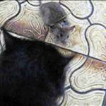
A very interesting discovery today. Windxtasy built her units and made a custom surround to hide the wiring (see pic of her hand cut effort). I thought it was a good idea so adapted my 3D print to include the trim panel. The result makes it look much more professional.
However, Windxtasy had only made a cutout for one unit and noticed while she was playing the unit without the 'trim' was ghosting a lot more than the other. I tried my units and sure enough in direct bright Perth sun without the trim, the units ghost, put the trim on and the contrast is near perfect. Interestingly, the unit screens don't ghost when off, so some sort of 'active effect.
The attached picture shows me holding the trim on one of my epoxy'd units in direct sun, then dropping the trim and taking another photo about 1 second later. I thought the light sensor might be the little round hole on the right of the battery indicator but covering that doesn't seem to do anything. I've uploaded the modified 3d Print files at www.prusaprinters.org/prints/151584-improved-doppler-windsurfing-gps-with-less-ghostin (of course you can just get the same dramatic improvement by just cutting some foam rubber similar to photos if you are using different housing). (Note at time of posting this I've printed the files and done a test fit with electronics but have not assembled and epoxy'd so there is small chance off design errors. The 3d prints are a look a little rough in photo as straight off printer with no finishing effort)


Raymond W, the developer or the "Gyro" gps, had a similare experience with a e-paper :
forum.windsurfing.nl/viewtopic.php?p=7448202#p7448202
Translated in English :
"At home everything works fine, you are standing by the water and the display is slowly fading. Reseat everything in the car and it works again. Until you get off WTF :wtf: After doing that 3 times and thinking logically: the flat cable can't stand sunlight (<-- :eek: ) Btje duck tape and I could test"
So it seems that the flat cable has to be protected against direct sunlight !
I have the same experience with my units, the BN is the worst with direct sunlight ! Gonna try it out.
Select to expand quoterp6conrad said..
Raymond W, the developer or the "Gyro" gps, had a similare experience with a e-paper :
forum.windsurfing.nl/viewtopic.php?p=7448202#p7448202
Translated in English :
"At home everything works fine, you are standing by the water and the display is slowly fading. Reseat everything in the car and it works again. Until you get off WTF :wtf: After doing that 3 times and thinking logically: the flat cable can't stand sunlight (So it seems that the flat cable has to be protected against direct sunlight !
I have the same experience with my units, the BN is the worst with direct sunlight ! Gonna try it out.
That makes sense. I did find that if you covered the right side of the screen all was well. Covering the top or bottom made no difference.
The dark surround solves the problem and makes it all look tidy too
Select to expand quoterp6conrad said..
the flat cable can't stand sunlight (So it seems that the flat cable has to be protected against direct sunlight !
Are you talking about the cable that's on the right of the screen in the picture of the blue GPS above?
I suspect that the controller on the e-paper itselfs is influenced by the UV-light of the sun (remember we used to erase eproms with uv light). The e-paper on the picture suffered from water-ingress, but you can see where the controller is located. The flat-cable itselfs is only for the communication between the esp32 and the e-paper controller, so my guess the controller is the reason of contrast issues. I will do a test with some black tape only on this controller, as soon as we have here some sun I will post the results.


Yes, can verify Jan's tests. That tiny rectangular strip is photosensitive. Covering it with a tiny piece of tape stops all signs of ghosting.


Legendary! nice find, I get this on one of my units (or is it one side of my boom).
Many moons ago on a product I was working on- taking a photo of it with the camera flash on would completely crash the LCD controller.
foil, or black tape solves the problem.
All transistors are phototransistors- so you have to block/control light if you don't want that "feature".
The chip on the FPC is not optically shielded very well- if you put enough light onto them. Depending on which transistors get affected you could get some interesting outcomes.
^^^ In the thermal part of the spectrum, for sure. Transistors (particularly MOSFETS and FETS) specifications change significantly with temperature. I would say most of the smarts in amplification and measurement is in the temperature stability and compensation. Secondly, the problem with enclosures is heat exchange. It does not take long for something like an ESP32 to heat up the inside of a small enclosure. Then add the sun and a hot day.
Select to expand quotejn1 said..
^^^ In the thermal part of the spectrum, for sure. Transistors (particularly MOSFETS and FETS) specifications change significantly with temperature. I would say most of the smarts in amplification and measurement is in the temperature stability and compensation. Secondly, the problem with enclosures is heat exchange. It does not take long for something like an ESP32 to heat up the inside of a small enclosure. Then add the sun and a hot day.
nah... not thermal. Photons inject induce additional carriers into the junction that cause "leakage", causing fets or BJTs to switch on when they shouldn't, and making logic become illogical.
Select to expand quotejn1 said..
^^^ In the thermal part of the spectrum, for sure. Transistors (particularly MOSFETS and FETS) specifications change significantly with temperature. I would say most of the smarts in amplification and measurement is in the temperature stability and compensation. Secondly, the problem with enclosures is heat exchange. It does not take long for something like an ESP32 to heat up the inside of a small enclosure. Then add the sun and a hot day.
my units weren't even closed or sealed yet, and I was only in the sun for long enough to get out of the range of my home wifi!
Select to expand quoteslowboat said..
nah... not thermal. Photons inject induce additional carriers into the junction that cause "leakage", causing fets or BJTs to switch on when they shouldn't, and making logic become illogical.
Ok. News to me ! (I'm an Electronics Technician by trade. Disclaimer: I don't know everything ! ![]() ). I agree with you that an exposed transistor junction would be affected by light. But the packages (with the exception to photo transistors and diodes) are enclosed in an epoxy enclosure that blocks light. However, heat can penetrate this enclosure (this is why we see wild parameter ranges in data sheets), and the sun produces energy in the thermal spectrum as well as light. Barrier potentials with different doping are tuned to different bands of the spectrum, but they all ultimately respond to thermal and light frequencies. I'm guessing without some metrological grade photo filters, this would be difficult to eliminate heat effect in a test. However, I will take your word for it and do some study. Do you have any research papers based on this ? (ie that discusses the limitations of electronic packaging ?)
). I agree with you that an exposed transistor junction would be affected by light. But the packages (with the exception to photo transistors and diodes) are enclosed in an epoxy enclosure that blocks light. However, heat can penetrate this enclosure (this is why we see wild parameter ranges in data sheets), and the sun produces energy in the thermal spectrum as well as light. Barrier potentials with different doping are tuned to different bands of the spectrum, but they all ultimately respond to thermal and light frequencies. I'm guessing without some metrological grade photo filters, this would be difficult to eliminate heat effect in a test. However, I will take your word for it and do some study. Do you have any research papers based on this ? (ie that discusses the limitations of electronic packaging ?)
Select to expand quotejn1 said..slowboat said..
nah... not thermal. Photons inject induce additional carriers into the junction that cause "leakage", causing fets or BJTs to switch on when they shouldn't, and making logic become illogical.
Ok. News to me ! (I'm an Electronics Technician by trade. Disclaimer: I don't know everything ! ![]() ). I agree with you that an exposed transistor junction would be affected by light. But the packages (with the exception to photo transistors and diodes) are enclosed in an epoxy enclosure that blocks light. However, heat can penetrate this enclosure (this is why we see wild parameter ranges in data sheets), and the sun produces energy in the thermal spectrum as well as light. Barrier potentials with different doping are tuned to different bands of the spectrum, but they all ultimately respond to thermal and light frequencies. I'm guessing without some metrological grade photo filters, this would be difficult to eliminate heat effect in a test. However, I will take your word for it and do some study. Do you have any research papers based on this ? (ie that discusses the limitations of electronic packaging ?)
). I agree with you that an exposed transistor junction would be affected by light. But the packages (with the exception to photo transistors and diodes) are enclosed in an epoxy enclosure that blocks light. However, heat can penetrate this enclosure (this is why we see wild parameter ranges in data sheets), and the sun produces energy in the thermal spectrum as well as light. Barrier potentials with different doping are tuned to different bands of the spectrum, but they all ultimately respond to thermal and light frequencies. I'm guessing without some metrological grade photo filters, this would be difficult to eliminate heat effect in a test. However, I will take your word for it and do some study. Do you have any research papers based on this ? (ie that discusses the limitations of electronic packaging ?)
sorry for getting way OT![]()
Normally the black/grey epoxy/plastic packaging that semiconductors come in is thick enough andhasenough pigment to block the light. IR certainlydoeshave an effect but thats different to conducted heat. Temperature sensitivity (conducted) of devicesdepends on the topology- the mechanisms are pretty complex but well defined, and causevoltage thresholds/gainto change a lotwith temperature- hence the significant sensitivity of device parameters to temperature. Then theres thermal noise, and changes in capacitance due to thermal expansion etc which affect timing and filters... but getting waaaay OT now. Most chips operate fine to way above their ratings- die temps of 120C etc usually function OK... Our LCDs are not getting anywhere near that hot (they would melt I think).
The high density COF packaging (chip on flex: no not you jim- I didn't see any chips on you today) is much thinner, and often to save cost they are glued onto the flex PCB with underfill, with no capping at all. The die is basically exposed so not much stops the light. The T5 LCD COF chip is capped with thin white but opaque silicon and you can see the die through it, so light gets straight into it.
By the time these devices find themselves in a product, they are (always)packaged in a metal or plastic bevel that hides the glorious details to make it pretty, so bonus it doesn't crash in the sun (or with a camera flash).
edit- not sure why the spacing went haywire- I think a camera flash must have gone off nearby...
Very nice catch. I saw the impact of the sun as well. Not as much though. But good to know that blocking part of the screen will solve it.
I had some good progress on customizing the stats screens in the software. I understand there are 2 types of speedsurfers. The ones that jibe and make miles and the ones that step off and check their run. Jan his stat screens are for the ones that make miles. I'm don't have the stamina so usually step off. So I have some time to have a good look and can make the fonts smaller and lot more information on the screen. Similar to the Gyro.
After some struggles I managed to have it working on the latest firmware from Jan. Tested it yesterday dan approved it. There is always details left but it is fully workable.
Now what's remaining is the case. Looking for an upper arm attachment and not on the boom as some of you. I really liked the 3d printed an balanced one from Flex2. Smallest footprint does not make it more easy to wear so I decided to move the GPS antenna on top of the screen with the battery below. But under an angle such There is a natural rounding of the arm. What is left are the holes for the elastic velcro strap around the arm. The 3d printed case need to be sealed with epoxy to make it water tight and the lid to be sealed with an o-ring similar to the standard purchased case that everybody is using. This was the first prototype. You can still see the tape to hold it in position ![]() . We're working on the 2nd version that is flatter, beveled corners, with screw inserts and o-ring seal. This was just to see how it would look. We might go with the plexiglass inside rather than on top, to keep it from scratching. Hopefully still as durable and watertight.
. We're working on the 2nd version that is flatter, beveled corners, with screw inserts and o-ring seal. This was just to see how it would look. We might go with the plexiglass inside rather than on top, to keep it from scratching. Hopefully still as durable and watertight.

Nice one Freezer. Your unit looks good. I was starting a similar design for shoulder/helmet mounting that has similar angle (toying with the idea of making the angle adjustable for different sized arms and helmet). I ordered some bits and whilst waiting for them to arrive came across another variable (discovered whilst talking Windxtasy through her build). That is the polarity of the wireless charge receivers.
This is important if you try and design something both slimline and easy to build (the wireless charge soldering is probably the hardest connection to make which might put some off) so using the plug and play USB connection is much easier...the USB's come in two orientations so need to know which one to get.
I have two types of receiver and two types of charge mat. All only work one way. i.e. first photo (electronics up) works, but second photo (electronics down) doesn't. So for me its important to load the correct way when assembling the unit. However, Windxtasy's receivers work both ways on the charge mat. Verified by measuring 5V and the charge mat indicator. She bought from the same supplier I suggested so I can only think her charge mat is superior to mine. My phone only charges one way (screen up). Our charge mats are all 10W.
This might be an issue for those lucky enough that it works both ways so they assemble unit one way. However if they then use a different charge mat (old one fails etc) they might find the unit doesn't charge. For this reason it seems better to assemble so they are oriented as per first photo. I could not find any reference to polarity of receiver or transmitter in the Qi standard but I didn't look very hard and thought I'd ask here.
Anyone know if Windxtasy coil/mat combo are a fluke? Or, what to look for in a charge mat that works both ways?
PS Not sure what you are refraining to with Jan's software only being for one type of sailor. You get nice realtime stats whilst sailing (changeable/selectable whilst sailing and not stopping) and 4 screens of stats when you stop/crash. Now an additional/resettable 2 stats screens of last 5 runs with the addition of second button/reed switch. So seems plenty of data for both types of sailor (although I'm nagging Jan to add some more realtime stats).


G'day Flex
The phone charge QI have a ferrite shield over the coil on one side (you can see it's outline on second photo).
Select to expand quoteslowboat said..jn1 said..slowboat said..
nah... not thermal. Photons inject induce additional carriers into the junction that cause "leakage", causing fets or BJTs to switch on when they shouldn't, and making logic become illogical.
Ok. News to me ! (I'm an Electronics Technician by trade. Disclaimer: I don't know everything ! ![]() ). I agree with you that an exposed transistor junction would be affected by light. But the packages (with the exception to photo transistors and diodes) are enclosed in an epoxy enclosure that blocks light. However, heat can penetrate this enclosure (this is why we see wild parameter ranges in data sheets), and the sun produces energy in the thermal spectrum as well as light. Barrier potentials with different doping are tuned to different bands of the spectrum, but they all ultimately respond to thermal and light frequencies. I'm guessing without some metrological grade photo filters, this would be difficult to eliminate heat effect in a test. However, I will take your word for it and do some study. Do you have any research papers based on this ? (ie that discusses the limitations of electronic packaging ?)
). I agree with you that an exposed transistor junction would be affected by light. But the packages (with the exception to photo transistors and diodes) are enclosed in an epoxy enclosure that blocks light. However, heat can penetrate this enclosure (this is why we see wild parameter ranges in data sheets), and the sun produces energy in the thermal spectrum as well as light. Barrier potentials with different doping are tuned to different bands of the spectrum, but they all ultimately respond to thermal and light frequencies. I'm guessing without some metrological grade photo filters, this would be difficult to eliminate heat effect in a test. However, I will take your word for it and do some study. Do you have any research papers based on this ? (ie that discusses the limitations of electronic packaging ?)
sorry for getting way OT![]()
Normally the black/grey epoxy/plastic packaging that semiconductors come in is thick enough andhasenough pigment to block the light. IR certainlydoeshave an effect but thats different to conducted heat. Temperature sensitivity (conducted) of devicesdepends on the topology- the mechanisms are pretty complex but well defined, and causevoltage thresholds/gainto change a lotwith temperature- hence the significant sensitivity of device parameters to temperature. Then theres thermal noise, and changes in capacitance due to thermal expansion etc which affect timing and filters... but getting waaaay OT now. Most chips operate fine to way above their ratings- die temps of 120C etc usually function OK... Our LCDs are not getting anywhere near that hot (they would melt I think).
The high density COF packaging (chip on flex: no not you jim- I didn't see any chips on you today) is much thinner, and often to save cost they are glued onto the flex PCB with underfill, with no capping at all. The die is basically exposed so not much stops the light. The T5 LCD COF chip is capped with thin white but opaque silicon and you can see the die through it, so light gets straight into it.
By the time these devices find themselves in a product, they are (always)packaged in a metal or plastic bevel that hides the glorious details to make it pretty, so bonus it doesn't crash in the sun (or with a camera flash).
edit- not sure why the spacing went haywire- I think a camera flash must have gone off nearby...
Sorry Slowboat. You are right. We are talking about TFT technology ?, which these epaper devices are, and not enclosed semiconductor tech. Totally agree with you. Sorry all for being a distraction and going off topic. Massive brain fart my end. "Shut up Jason".
Select to expand quotejn1 said..slowboat said..jn1 said..slowboat said..
nah... not thermal. Photons inject induce additional carriers into the junction that cause "leakage", causing fets or BJTs to switch on when they shouldn't, and making logic become illogical.
Ok. News to me ! (I'm an Electronics Technician by trade. Disclaimer: I don't know everything ! ![]() ). I agree with you that an exposed transistor junction would be affected by light. But the packages (with the exception to photo transistors and diodes) are enclosed in an epoxy enclosure that blocks light. However, heat can penetrate this enclosure (this is why we see wild parameter ranges in data sheets), and the sun produces energy in the thermal spectrum as well as light. Barrier potentials with different doping are tuned to different bands of the spectrum, but they all ultimately respond to thermal and light frequencies. I'm guessing without some metrological grade photo filters, this would be difficult to eliminate heat effect in a test. However, I will take your word for it and do some study. Do you have any research papers based on this ? (ie that discusses the limitations of electronic packaging ?)
). I agree with you that an exposed transistor junction would be affected by light. But the packages (with the exception to photo transistors and diodes) are enclosed in an epoxy enclosure that blocks light. However, heat can penetrate this enclosure (this is why we see wild parameter ranges in data sheets), and the sun produces energy in the thermal spectrum as well as light. Barrier potentials with different doping are tuned to different bands of the spectrum, but they all ultimately respond to thermal and light frequencies. I'm guessing without some metrological grade photo filters, this would be difficult to eliminate heat effect in a test. However, I will take your word for it and do some study. Do you have any research papers based on this ? (ie that discusses the limitations of electronic packaging ?)
sorry for getting way OT![]()
Normally the black/grey epoxy/plastic packaging that semiconductors come in is thick enough andhasenough pigment to block the light. IR certainlydoeshave an effect but thats different to conducted heat. Temperature sensitivity (conducted) of devicesdepends on the topology- the mechanisms are pretty complex but well defined, and causevoltage thresholds/gainto change a lotwith temperature- hence the significant sensitivity of device parameters to temperature. Then theres thermal noise, and changes in capacitance due to thermal expansion etc which affect timing and filters... but getting waaaay OT now. Most chips operate fine to way above their ratings- die temps of 120C etc usually function OK... Our LCDs are not getting anywhere near that hot (they would melt I think).
The high density COF packaging (chip on flex: no not you jim- I didn't see any chips on you today) is much thinner, and often to save cost they are glued onto the flex PCB with underfill, with no capping at all. The die is basically exposed so not much stops the light. The T5 LCD COF chip is capped with thin white but opaque silicon and you can see the die through it, so light gets straight into it.
By the time these devices find themselves in a product, they are (always)packaged in a metal or plastic bevel that hides the glorious details to make it pretty, so bonus it doesn't crash in the sun (or with a camera flash).
edit- not sure why the spacing went haywire- I think a camera flash must have gone off nearby...
Sorry Slowboat. You are right. We are talking about TFT technology ?, which these epaper devices are, and not enclosed semiconductor tech. Totally agree with you. Sorry all for being a distraction and going off topic. Massive brain fart my end. "Shut up Jason".
haha no worries- none of the other engineers I work with knew about this. And they are making stuff with LCDs at the moment. Its cool that the GPS crew found and fixed this too. Jan's pics above show where it is on the displays used here. On other devices its a mirror finish grey/black "chip" stuck onto the flex pcb. Thats the unencapsulated type. And its not just TFTs or epaper- its anything using these chips (plenty in modern phones for example).
Select to expand quoteelmo said..
G'day Flex
The phone charge QI have a ferrite shield over the coil on one side (you can see it's outline on second photo).
the ferrite tape "shield" should go on the other side of the coil from the charger- otherwise it reduces the magnetic field in the coil (it might still work a bit but not very well).
Basically the high permeability compared to air (and other material behind the coil) shunts the magnetic field and directs it right back to/from the charging pad.
See www.mouser.com/pdfDocs/Wurth-Going-Wireless-with-Magnetic-Shielding.pdf
Select to expand quoteFlex2 said..
Nice one Freezer. Your unit looks good. I was starting a similar design for shoulder/helmet mounting that has similar angle (toying with the idea of making the angle adjustable for different sized arms and helmet). I ordered some bits and whilst waiting for them to arrive came across another variable (discovered whilst talking Windxtasy through her build). That is the polarity of the wireless charge receivers.
This is important if you try and design something both slimline and easy to build (the wireless charge soldering is probably the hardest connection to make which might put some off) so using the plug and play USB connection is much easier...the USB's come in two orientations so need to know which one to get.
I have two types of receiver and two types of charge mat. All only work one way. i.e. first photo (electronics up) works, but second photo (electronics down) doesn't. So for me its important to load the correct way when assembling the unit. However, Windxtasy's receivers work both ways on the charge mat. Verified by measuring 5V and the charge mat indicator. She bought from the same supplier I suggested so I can only think her charge mat is superior to mine. My phone only charges one way (screen up). Our charge mats are all 10W.
This might be an issue for those lucky enough that it works both ways so they assemble unit one way. However if they then use a different charge mat (old one fails etc) they might find the unit doesn't charge. For this reason it seems better to assemble so they are oriented as per first photo. I could not find any reference to polarity of receiver or transmitter in the Qi standard but I didn't look very hard and thought I'd ask here.
Anyone know if Windxtasy coil/mat combo are a fluke? Or, what to look for in a charge mat that works both ways?
PS Not sure what you are refraining to with Jan's software only being for one type of sailor. You get nice realtime stats whilst sailing (changeable/selectable whilst sailing and not stopping) and 4 screens of stats when you stop/crash. Now an additional/resettable 2 stats screens of last 5 runs with the addition of second button/reed switch. So seems plenty of data for both types of sailor (although I'm nagging Jan to add some more realtime stats).
My wireless coil has a much smaller PCB than yours, looks about 1/3rd the size, so it is obviously a different model.
can't take a photo because it is at home. It works both ways but I have orientated it like your first pic because it fits in the box with the better that way