Select to expand quoteboardsurfr said..decrepit said..
That case of yours, looks great, with a big clamp.
Does it have a name?
The one in the picture is an Otterbox Pursuit 20 I bought in 2013. They don't seem to make this anymore. If I'd use it on the water, I'd put all the electronics inside a zipper bag. With the Pi Zero, all the parts are small and thin. Maybe I'll gut an old Android phone I have and use the shell to put stuff in :-).kato said..
Is all that hooked up to a phone as well ??.
No, but theoretically, it could send data to a phone over Bluetooth. Not sure how attractive that is, since you'd have to wear two armbands. It would be easier to add some kind of display to the Pi, although that probably would break the plug-and-play simplicity.
There are options for plug and play screens......here are just few:
You can get solder less GPIO headers like these www.adafruit.com/product/3413
Then you could add an e ink screen like this www.adafruit.com/product/3335
Being ePaper / eInk (like a kindle) it would have good contrast in the sun and retain the last screen dump forever even when the Pi shuts down and the power is removed.
If you wanted a user interface then this one www.adafruit.com/product/3531 might be better, but it would have to be housed in a flexible waterproof case so you could press the buttons!
There are also LCD touch screens but you would have to confirm they work in sunlight..... viewing my phone (with LCD screen) while out on the water is sometimes impossible on a sunny day!
I have a 3.5 in touch screen which fits the Pi 3 very well, but would be a bit big for the Pi Zero. Works with just the HDMI cable if you want it as a display only, but has a number of limitations. Besides poor visibility in the sun, it draws 200 mA even at low resolution and brightness, which would cut battery life to 1/3rd. An e-ink display may be the way to go. The Adafruit one likes like a great fit. Costs about as much as the Pi + GPS + battery, but the total is still in the same ballpark as a Canmore ![]() . Even if I'd never look at the numbers, having a visual indication that the Pi is logging would be nice.
. Even if I'd never look at the numbers, having a visual indication that the Pi is logging would be nice.
The price is on the high side, unfortunately after quick look around google, Adafruit seemed to have the best price![]()
What I did miss is the display does have 5 switches on it![]()
There is a review of the screen here raspi.tv/2016/playing-with-papirus-zero
No doubt other cheaper screens that could be used. The beauty of the PI and availability of Pi hats is the end user can choose what to put on, assuming the hard work with the software + testing has already been done! OR others with skills in software can develop and add to the project.
My day job is mainly hardware and some embedded software (C code) design, I have never used Java or a python script but this project you have started has got me thinking it could be good to get a Pi and tinker with some Java over the winter months.
Select to expand quotesrtgumbee said..
>>>>> I have never used Java or a python script but this project you have started has got me thinking it could be good to get a Pi and tinker with some Java over the winter months.
Fantastic, the more tinkerers on this project the better!!!!
Peter is doing a great job, for those who just want to plug and play. But it would be good to explore other alternatives
Select to expand quotesrtgumbee said..
My day job is mainly hardware and some embedded software (C code) design, I have never used Java or a python script but this project you have started has got me thinking it could be good to get a Pi and tinker with some Java over the winter months.
Or you could stick with Python. So far, my code is rather trivial - read from the serial/USB port, write to a file (plus a bit of writing to the port to configure the dongle). That should be pretty straightforward in Python, too. I have seen some Python code to handle the ublox chip. Don't recall where, but probably was related to drones.
The only reason why I used Java was that I'm familiar with it, while I barely know Python. Also, I could reuse bits of code I had already developed for Android before. I I'd have to learn both for working with Linux, I'd probably pick Python these days.
Thanks, will look into using Python ![]() . Be good to get into something new over the June - August months.
. Be good to get into something new over the June - August months.
With regards to a water proof case to house the electronics for a Pi data logger or a Bluetooth sender.
How about an action cam case? this pic taken from an old forum www.iwindsurf.com/forums/viewtopic.php?t=21896&postdays=0&postorder=asc&start=0&sid=7eaf76e7ed3d3bd9d1c686d848f803ed 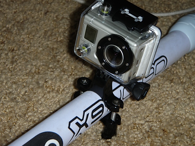
The cases can be bought for $5-15, come with heaps of attachments are are known to be waterproof.
The Pi has similar dimensions to the latest china action cams so I think they will have enough space inside.
If you can imagine the GPS antenna placed where the camera lens is, then in the configuration shown in the pic, the case could be tilted so it is looking to the sky and might allow the smaller antennas (eg USB dongles) to perform as well as the larger antennas. Body mounted (head) would be best for vibration to the electronics but a boom mount might also work out to be ok.
For those that have performed GPS testing, can you see a boom mount (anywhere on the boom) idea being a good option?
Select to expand quotesrtgumbee said..
Thanks, will look into using Python ![]() . Be good to get into something new over the June - August months.
. Be good to get into something new over the June - August months.
srtgumbee, I am rubbish at C, Java, and Python, but Python seems to be the easiest to me, and from what I can see, Python appears to be the 'default' language for most Pi projects. So I am with you, and I will also look at getting some Python code sorted during winter, but I am hoping there are some good libraries out there already. If you have any code wins, please post/PM me them, cos I am really lazy.![]()
Oh and as for the enclosure - similarly to the Go Pro idea, I am using a Sony Action Cam waterproof box and mounts on my helmet. I like to put my GPS unit there because it seems to be the place that I break/ damage the least. Booms are are a high risk area for me...![]()
The sensible thing to do is hijack someone's already water proof box and within reason build electronics to fit. I mentioned the lifeproof phone cases on another thread (simon100 was entertaining the idea of a GPS).
Gath Helmets in Margaret River WA is working on an intercom system incorporated into their Gedi helmet for coaching purposes. They might be able to assist with water proof box & helmet combination. I might even enquirer.
If I knew electronics I'd be all over this but I'm not going there.
So guys please continue with your investigations for those of us here on the fence. I don't understand much but it's an interesting read.
Cheers Dave
Select to expand quotesrtgumbee said..
>>>>>> For those that have performed GPS testing, can you see a boom mount (anywhere on the boom) idea being a good option?
Might be OK on the straight, but I think it will swing around too much in the gybes for an accurate alpha.
The head is certainly the best place. A custom made Gath would be great.
Select to expand quotedecrepit said..
Thanks Andrew, $20 with faster postage, didn't want to wait until June!
But no USB, I'l have to figure out how to connect an adapter, but that shouldn't be too hard.
OK I've read the manuals and it's not supper easy. Well and truly destroys Peters idea of plug and play.
I'll have to modify the board a bit, change the pin outs from "RX and TX" to USB terminals on the chip and add some more components. The M8 works at a max of 3.3v so a regulator is needed to knock down the USB 5v. Until the module arrives I've no idea if I can fit this stuff on the module or if I'll need a small additional board, I suspect the latter. The module could be a month away, so don't hold your breath waiting for this outcome.
But if somebody else comes up with code that's designed for the RX and TX terminals, that will save some work.
All this talk of microcontrollers and GPS modules has got me interested. I have so many bits of Arduino lying around I figured it might be an interesting project to hook up a GPS module, and write it to SD.
So, I bought a M8N module, stripped the connectors and wired it up to a USB to serial (3.3v) converter. It now finds where I am in u-center, so I know the comms is working. I wasn't sure about RX and TX initially and the default baudrate. TxD is an output and RxD is an input. Don't laugh, but sometimes they refer to the device and sometimes the terminal, so it could have been one way or the other. The default baud rate appears to be 38400.
So, now that I have it connected and working, at least in u-center, what data do I need out of it in order to be sufficient for speed sailing. I know its not from a certified device, but what information do I need it to send and what can I use to then process the data? In other words, what Windows program can then interpret it to be something meaningful?
Any pointers?
Select to expand quoteFormulaNova said..
>>>>> I know its not from a certified device, >>>>
Well not yet, but if you get it working and recording a .ubx file with doppler and accuracy data, then it shouldn't take much to get it approved.
Select to expand quotedecrepit said..FormulaNova said..
>>>>> I know its not from a certified device, >>>>
Well not yet, but if you get it working and recording a .ubx file with doppler and accuracy data, then it shouldn't take much to get it approved.
Thanks. What program do you then use to look at the UBX log file?
I think old realspeed may be the only one that doesn't handle it. GPSResults, GPSARPro and KA72 all process it no worries.
Select to expand quotedecrepit said..
I think old realspeed may be the only one that doesn't handle it. GPSResults, GPSARPro and KA72 all process it no worries.
Thanks. I will check those out. The u-center tool is pretty cool. I guess they created it to encourage people to use their GPS chips.
Right now I seem to have configured the M8N to do (51ms) 19.61Hz updates. I don't know if its actually capable of that, but that's what the utility seems to let me set.
I guess I have some reading up on the UBX protocol to do... ![]()
Select to expand quoteFormulaNova said..decrepit said..
I think old realspeed may be the only one that doesn't handle it. GPSResults, GPSARPro and KA72 all process it no worries.
Thanks. I will check those out. The u-center tool is pretty cool. I guess they created it to encourage people to use their GPS chips.
Right now I seem to have configured the M8N to do (51ms) 19.61Hz updates. I don't know if its actually capable of that, but that's what the utility seems to let me set.
I guess I have some reading up on the UBX protocol to do... ![]()
As far as I know it does 5, 10 and 18hz.
Feed back from other guys says there's not much extra value in 18hz, and it creates very big files, that the software takes ages to process.
I think it also excludes gonass sats.
The device needs to be set to record the following ubx sentences from the M8:
The 3 sentences we need are (from Manfred):
In u-blox 8, NAV-PVT and NAV-DOP should be used and are parsed by the app at the full rate, NAV-SAT should be adjusted for 1 Hz.
The ublox M8n will use 2 GNSS at up to 10Hz (GPS and Glonass). At 18Hz it can only use one GNSS (GPS).
Roo and Manfred have reported excellent results @18Hz, but I have found 10Hz suits me better with smaller files and slightly better number of sats. My phones have trouble with missing data points at 18Hz, (even after we upped the baud rate) but apparently, better phones can do it fine.
Select to expand quotesailquik said..
The device needs to be set to record the following ubx sentences from the M8:
The 3 sentences we need are (from Manfred):
In u-blox 8, NAV-PVT and NAV-DOP should be used and are parsed by the app at the full rate, NAV-SAT should be adjusted for 1 Hz.
The ublox M8n will use 2 GNSS at up to 10Hz (GPS and Glonass). At 18Hz it can only use one GNSS (GPS).
Roo and Manfred have reported excellent results @18Hz, but I have found 10Hz suits me better with smaller files and slightly better number of sats. My phones have trouble with missing data points at 18Hz, (even after we upped the baud rate) but apparently, better phones can do it fine.
Hi Andrew, thanks. I also found something in a GPS Speed sailing document where I think you mentioned 'UBX sequence 0112 at 10hz'. Is this NAV-VELNED or something else? Is this required?
I also found an earlier post from last year I think which talked about NAV-STATUS. Is that needed as well?
Select to expand quoteFormulaNova said..sailquik said..
The device needs to be set to record the following ubx sentences from the M8:
The 3 sentences we need are (from Manfred):
In u-blox 8, NAV-PVT and NAV-DOP should be used and are parsed by the app at the full rate, NAV-SAT should be adjusted for 1 Hz.
The ublox M8n will use 2 GNSS at up to 10Hz (GPS and Glonass). At 18Hz it can only use one GNSS (GPS).
Roo and Manfred have reported excellent results @18Hz, but I have found 10Hz suits me better with smaller files and slightly better number of sats. My phones have trouble with missing data points at 18Hz, (even after we upped the baud rate) but apparently, better phones can do it fine.
Hi Andrew, thanks. I also found something in a GPS Speed sailing document where I think you mentioned 'UBX sequence 0112 at 10hz'. Is this NAV-VELNED or something else? Is this required?
I also found an earlier post from last year I think which talked about NAV-STATUS. Is that needed as well?
I don't know what that first one is.
NAV-Status is not needed. In fact I have a sneaking suspicion we now may only need two of those sentences from the M8. I will go back through my notes and check.
The ubx sentences needed from the M6 and M7 are slightly different as the info in some of the sentences changed with the M8.
Select to expand quotedecrepit said..decrepit said..
Thanks Andrew, $20 with faster postage, didn't want to wait until June!
But no USB, I'l have to figure out how to connect an adapter, but that shouldn't be too hard.
OK I've read the manuals and it's not supper easy. Well and truly destroys Peters idea of plug and play.
I'll have to modify the board a bit, change the pin outs from "RX and TX" to USB terminals on the chip and add some more components. The M8 works at a max of 3.3v so a regulator is needed to knock down the USB 5v. Until the module arrives I've no idea if I can fit this stuff on the module or if I'll need a small additional board, I suspect the latter. The module could be a month away, so don't hold your breath waiting for this outcome.
But if somebody else comes up with code that's designed for the RX and TX terminals, that will save some work.
The ebay Ublox m8n has a 3.3V regulator on it so it can handle 5V ok.......this is also why Andrew could power it straight off a Li-ion battery![]()
BUT, I have found that the product cannot easily be modified to allow a for simple USB connection. The major problem is there are three earth tracks on the VDD-USB pin that need to be cut, one is visible and can be cut, the other two are underneath the Ublox module and you can only access it by taking the module off the board with a heat gun, cutting the tracks and putting the module back on. Not a recommended solution.
The best way is to wire the Ublox straight to the GPIO serial pins of the PI Zero, But we don't have software for that yet.
The other way which may work (if Rasbian has the drivers installed) is to use a USB to serial converter. The Ublox serial goes to the serial of the converter and the USB goes to the PI though via a short Male micro USB to Male micro USB cable.
Select to expand quotesrtgumbee said..decrepit said..decrepit said..
Thanks Andrew, $20 with faster postage, didn't want to wait until June!
But no USB, I'l have to figure out how to connect an adapter, but that shouldn't be too hard.
OK I've read the manuals and it's not supper easy. Well and truly destroys Peters idea of plug and play.
I'll have to modify the board a bit, change the pin outs from "RX and TX" to USB terminals on the chip and add some more components. The M8 works at a max of 3.3v so a regulator is needed to knock down the USB 5v. Until the module arrives I've no idea if I can fit this stuff on the module or if I'll need a small additional board, I suspect the latter. The module could be a month away, so don't hold your breath waiting for this outcome.
But if somebody else comes up with code that's designed for the RX and TX terminals, that will save some work.
The ebay Ublox m8n has a 3.3V regulator on it so it can handle 5V ok.......this is also why Andrew could power it straight off a Li-ion battery![]()
BUT, I have found that the product cannot easily be modified to allow a for simple USB connection. The major problem is there are three earth tracks on the VDD-USB pin that need to be cut, one is visible and can be cut, the other two are underneath the Ublox module and you can only access it by taking the module off the board with a heat gun, cutting the tracks and putting the module back on. Not a recommended solution.
The best way is to wire the Ublox straight to the GPIO serial pins of the PI Zero, But we don't have software for that yet.
The other way which may work (if Rasbian has the drivers installed) is to use a USB to serial converter. The Ublox serial goes to the serial of the converter and the USB goes to the PI though via a short Male micro USB to Male micro USB cable.
Is VDD-USB really tied to ground? Does this disable the USB interface or just make supplying power via USB a problem?
Are you able to supply power via VCC and still use the USB data signals?
Select to expand quoteFormulaNova said..
Is VDD-USB really tied to ground? Does this disable the USB interface or just make supplying power via USB a problem?
Yep looks like it. In serial mode USB can't be used, and vice versa. Select to expand quote
1.3.3 VDD_USB: USB interface power supply
VDD_USB supplies the USB interface. If the USB interface is not used, the VDD_USB pin must be connected to
GND. For more information about correctly handling the VDD_USB pin, see section 1.4 Select to expand quote
Are you able to supply power via VCC and still use the USB data signals?
As I understand It, it says that in USB mode VCC isn't used
Both Pi and M8 module arrived today, must admit to being a bit surprised, The Chinese one said it would arrive a few weeks later.
As gumbee says, my idea of modifying the module was overly ambitious. The pictures give a false impression of size, the board and chip is much smaller than I had in my head. Even discounting having to remove and replace the chip, it would be very fine exacting work. I don't think either my eyesight is good enough or my hands steady enough now.
So it'll be a serial to USB converter experiment for starters.
Ublox Manual is here:
www.u-blox.com/sites/default/files/NEO-8Q-NEO-M8-FW3_HIM_%28UBX-15029985%29.pdf
USB section is on pages 7 & 8.
Quote " USB interface power supply VDD_USB supplies the USB interface. If the USB interface is not used, the VDD_USB pin must be connected to GND. "
I assumed the USB interface to be the Ublox's internal interface and I did not go on to try it out. Would not take much to try to be certain, may give that a go if I have time.
I am not sure which module you are using, but I bought one of the 'helicopter type' modules, and opened it up just to check the signals anyway. A lot of RC people use these so the pinouts online were correct anyway.
I opened it up again an hour ago, and like you found, the VDD pin appears to be tied to Gnd. Interestingly the USB data pins appear to go to an unused 8 pin chip location. I am not sure what that is meant for, but possibly an alternate connector if the same module was used for USB, although unless VDD is tied to GND through an optional resistor, that wouldn't make sense either.
The datasheets and everything else suggest that there is no restriction on using USB and serial at the same time. U-centre allows you to enable and disable different things for the different interfaces. It appears that you can even send different messages to different interfaces.
I believe that you can't use SPI and the UART at the same time though, given that they use the same pins ![]() I2C/DDC pins are available though and again you should be able to use that at the same time.
I2C/DDC pins are available though and again you should be able to use that at the same time.
Select to expand quotedecrepit said..
Both Pi and M8 module arrived today, must admit to being a bit surprised, The Chinese one said it would arrive a few weeks later.
As gumbee says, my idea of modifying the module was overly ambitious. The pictures give a false impression of size, the board and chip is much smaller than I had in my head. Even discounting having to remove and replace the chip, it would be very fine exacting work. I don't think either my eyesight is good enough or my hands steady enough now.
So it'll be a serial to USB converter experiment for starters.
Yeah, its not big! Just to probe the pins to check the VDD-USB pin I had to use a magnifier. As a kid I am sure I wouldn't have needed it, but these days I use a couple of magnifiers for this sort of work and they make a huge difference.