Fantastic work guy's, fangy was sorting out foundries and nutting out the fangy fillet a few years back before i stopped windsurfing, the fin looks great and a shame I'm not sailing to give it a blast ![]()
![]()
![]()
^Agree wholeheartedly with the sentiment. Keef was a major influence on my fin thinking - Standing on the Shoulders of Giants to see further' sort of thing so, whatever Keef has on his workbench right now will be all that is needed if he wants to get his bum wet again.![]()
Absolutely fangman, I'm a horder everything is still there ,there's a matter of putting it all together ![]()
I'm into modifying cars , but mite put the gear together for a warm windy westerly at primbee this winter, I have a new new shallow water fin to try,
Inspired years ago by the fangman but never got around to make it,
Keep up the good work your killing it ![]()
![]()
Tested the Green Machine FF22 3d print with flex trailing edge on pretty choppy Albany day yesterday with encouraging results. Unfortunately I hit a submerged object like a rock/razor clam early on. The 3d print was fine but turns out DiChloroMethane does not weld to mono film like it does with PETG so the trailing edge was pulled out of its slot about 2cm and flapping around. Had to get back and travelling 30-32kts in the weed meant the trailing edge was pulled further out. Used some scissors to cut the bottom 6cm or so off and continued sailing. Fin didn't feel quite as solid as before but at least the remaining trailing edge stayed in place for the rest of the day.
Spent the day swapping boards and between this fin and the regular Al Fangy. By a long way the 3d printed fin felt completed locked in and solid in chop both upwind and downwind. I spent a lot of time in the big chop areas trying to either make it break or spin out which it did neither. The regular Fangy spun out a lot more and felt quite dangerous in comparison. (Again, this fin is worn so it's not a true comparison).
Polars below tell more of the story. On big board (97litre) pointed 3 deg better upwind than regular Al Fangy before I hit the rock and lost the bottom 1/3 of flex edge. After that incident it it pointed the same as FF but Fangy was way sketchier/dangerous. Switching to the smaller 86 litre board, the damaged flex fin pointed better by 1 deg than the undamaged flex fin on larger board and a wopping 9 deg better than the regular FF. Even in the big chop in the middle on 2nd time out still did 3 deg better than the normal Al Fangy dealing with less chop. (this is on both tacks) Zero weed issues with no gasket, felt the safest on this fin and zero structural issues.... Top speed was also on the printed fin (33.79kt).
Already replaced the flexy edge using epoxy like previous fin to secure and need to test further/maybe borrow a fresh FF22 to compare before trying the idea on different fins etc. 

Had a good look at Flex's prints the other day, and I'm really impressed!
For a fangy type delta I think they are the optimum way to go.
The fin shape restricts flex enough. (on a pointer they'd need stiffening).
They are lighter than a fangy.
They are much cheaper and easier to make, (if you have a 3D printer), than any other process.
But most impressive is wear resistance, after extensive use at Lilacs, no sign of abrasion on the leading edge, apart from on the tip, due to too shallow water and rocks. Possibly not as good as my stainless leading edge, but it would be a close run thing between a flex and a fangy.
But just don't try and order one!
Buy a 3D printer and make your own.
Time for an update. I have been continuing to play with the FangyFin code that generates a 3D CAD model given and outline and some geometric parameters. It works reasonably well now, but is not particularly robust, so the code tends to fall over more often than it should. I added a Bambu 3D printer to the toys in the shed and have now progressed to churning out a fin or two. The fin below is to investigate higher chord thickness, (12%) coupled with an increased concavity in the trailing third of the profile.

I used Flex's technique of PETG filament shell filled with epoxy. The infill is 10% so it was a cinch to pour the resin. The carbon rod stiffeners are whatever diameter I could fit. I some cases I used old carbon sail battens filled with epoxy and then stuffed bundles of smaller diameter rods inside. I was aiming for slightly increased flexibility along the trailing edge, but super stiff in the main body. The stainless rods are epoxied in situ with no nut. The experiment here being to investigate whether the long section of thread will provide enough anchorage on its own. I have done away with preloading the printed PETG model under compression. I want to see if the high amount of carbon rod and epoxy can do all the heavy lifting in this layout.
I also attempted to print a Tuttlebox mould and create this section just by pouring resin. I failed spectacularly when I forgot to put separator on the inside of my mould. After cutting away the 3D print like a drunk blind man swatting mosquitos, the resulting tuttlebox is rather rough and ready. Next job is to get it wet. And if its worthy, finish and polish it up to a decent level and see how long it lasts.

Next cab off the rank is an experiment to compare the drag effects of foil thickness versus surface area/depth. When sailing in the weed the shorter the fin the less weed drag. Hence a fat foil that has enough lifting power, packaged it in an 18cm fin.
The foil has 125 per cent more lift than the fin above, but the surface area is only 75 per cent. In an ideal world, ignoring all the inefficiencies of outline, pressure leakage etc etc, I am hoping the total lift generated will be somewhere close enough to be able to compare weed drag versus pressure drag.
The fin in the post above is 24cm depth. The one below is 18 cm.
The 18cm has an even more pronounced profile concavity toward the trailing edge. (Second photo.)
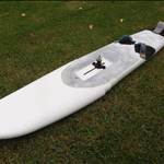
The 24cm fin above came in at just over a kilo. I decided to have a crack at shedding some more weight, so you can see the silhouette of the hollows for carbon rods and foam inserts. Despite the 20mm diameter hollows, the foil is thick enough that there is plenty of space laterally to fit in enough resin for strength (32mm thickness at max)- bottom photo. ( in the background is my apprentice Ernie)
3D printing - I am experimenting with increased wall thickness around my carbon rod holes. Given the PETG is reasonably good in compression, I thought I would see how a print with a higher percentage of filament material around the internal hollows fared.
The apparently massive fillet will be trimmed back. I enlarged the fillet to create a greater surface area on the print bed to increase the PETG adhesion and prevent warping.
I printed the first part of the fin on a hotter bed and nozzle temp, thicker first layer and at a slower speed. This seems to have been successful in keeping the base nice and flat.


Some thought bubble fins at varying stages of completion.,The FF22 is in the photos as a size reference.
The little fin is an experiment with an extremely thick profile, sandwiched into 18cm depth. Trying to generate lots of lift for light winds and shallow/weedy water. Was in the post above.

The biggest fin is 248mm depth. A massive 15% chord thickness, lots of trailing edge concavity. Trying to see if I can get FF28 levels of ability and control. The top 4 cms is sacrificial and to be replaced with an ellipsoid bulb once I get an idea of abilities/polar plots so I can compare.

The middle fin is unusual in that it has a almost constant thickness for two thirds of its span, that is, the % chord thickness increases slightly as you progress toward the tip until the final 1/3. There is less tip surface area. I want to see if the lift benefits compensate the expected drag.
The coupler on the front bolt is a result of a rookie mistake. I measured the length of bolt I needed to get to deck height on the thickest board. I cut at this length. I was left with a bolt that was beautifully flush with the deck... with no thread exposed for me to put the put the nut.![]()


Looking good Ross, you may have made just what I need, a very low aspect fin that works in wider boards.
See my light wind board thread
Select to expand quotedecrepit said..
Looking good Ross, you may have made just what I need, a very low aspect fin that works in wider boards.
See my light wind board thread
Oh snap! I was just posting on your thread. I will try these out and if they are not atrocious and worthy of investigation, fling them your way. Of course it relies on them not cracking/snapping/failing in the meantime.
Select to expand quoteBernoza said..
Hi Fangman
How can I get ahold of your fins?
Regard
Cameron (NSW)
I have sent a PM on SB Cameron.![]()
I have been boffinising over the past few months and churned out a number of fins to play with and evaluate. I will post them over the next month or so in no particular order.
The first few fins are experiments with biomimetics.
This first one is an FF25, 8% chord, 400cm^2 with a flexible trailing edge.
The body of the fin is translucent PETG filled with Bully Boy Basil's araldite brew. The leading edge is stiffened with carbon rod. With previous fins showing no sign of mischief with decreasing amounts of carbon rod, and they have in turn been replaced with eucalyptus dowel, I decided to try a full dowel construction. So in this model, the fin base and body are joined and strengthened with wood dowel and threaded rod only.
The trailing edge is an ellipsoid of TPU95 that is glued into the PETG base. The trailing edge is now able to twist off a little under heavy and shock loading. There is a more pronounced trailing edge concavity toward the base of the fin foil.


Select to expand quotedecrepit said..
wow. it's s work of art Fangy!
Hope it goes as good as it looks.
Given the number of mistakes/stuff ups/traps for newbies and general brain farts I am making while getting these things into the world, no one will be more surprised than me! ![]()
Nice Ross, what glue did you use to join PETG to TPU? Or TPU to anything? Nothing I've tried works properly. Tetrahedrofuran supposed to be the best but worse the Dichloromethane. That only lasted 30 secs though in windsurf application. Best seems to be heat welding. Went through 10 variations of TPU only fins trying to get balance between stiffness and flex, then other projects took over and currently on back burner. Should upload a video of lessons learnt...not sure if I will get around to it though...but if you have found a glue that works........?
This the fin I made a year ago...so far the most potential after the basic warp fin, super slippery...meant to be full Prandtl. Based on a super stiff mast and variable flexy airfoil. This one failed early as the mast failed about 1/3 from bottom which in turned ripped the PETG airfoil. Took another 9 fins to solve the mast issue and ran that on a TPU only fin with roughly the same concept...it was a dog though..since then working on other stuff


Select to expand quoteFlex2 said..
Nice Ross, what glue did you use to join PETG to TPU? Or TPU to anything? Nothing I've tried works properly. Tetrahedrofuran supposed to be the best but worse the Dichloromethane. That only lasted 30 secs though in windsurf application. Best seems to be heat welding. Went through 10 variations of TPU only fins trying to get balance between stiffness and flex, then other projects took over and currently on back burner. Should upload a video of lessons learnt...not sure if I will get around to it though...but if you have found a glue that works........?
A slight bit of undercut and compression so that the TPU is physically locked into the guts of the fin. I then used Fat Bully Boy Basil's Brew of araldite and an occasional hapless small insect to bond it all together. Originally, I had the threaded rod piercing the front section of the TPU to act as a rudder post, so if this version falls apart in short order I will revert to physically anchoring. ( assuming it's worth doing at all!)
I have a full TPU fin variant almost done so I will post that one soon.
Next up is the full TPU print. TPU has s stiff rubbery-like consistency. I wanted to try to build a fin where the surface of the foil would deform slightly in response to the local pressure. The entire fin in TPU only would be far too flexible, but when filled with epoxy and stiffening rods, I thought I might have something that was biomimetic.
The first iteration was too flexible in the tip due to my lay out of carbon rods being focused on keeping the base part of the fin very stiff and strong. This mistake forced a visit to the cheap and nasty modifications bench. In order not to compromise the rods already in place, I attempted to place a big galvanised screw through from the top of the fin. This was hard to do, and the screw kept wandering off centre because of the layout of the gyroid infill. This approach is not recommended.![]()
In the end I cut a slot, inserted the screw, and epoxied it in place. I feathered the resin over the surface as well. This has led to the surface being less pliable around and along the screw, which is not ideal. However, the fin is nice and stiff along the wingspan. I plan to slowly polish off the resin top coat and see if I can pick any change in performance. I expect at some stage the epoxy rod section will separate from the TPU due to their disparate flex characteristics. If the TPU fin shows any promise, I will redo from scratch and insert a carbon longitudinal rod from the base at the time of construction.

The next fin is FF30 with a shorter base chord and rake of 36 degrees. I printed this one in PLA.
PLA is the cheapest print material. It is reasonably strong and easy to print. It is not particularly flexible and tends to snap. It is not happy with UV or prolonged water exposure.
To counter this I have encased the PLA in a couple of thin coats of epoxy. The photo shows the fin prior to final sanding and finishing.
I had some small issues with warping at the join. Over the next few fins, I have modified my printing techniques to minimise the issue. The cut line was placed at perpendicular to the leading edge. The effect is to place the print layers diagonal to the flow
The purpose of this fin is to see if the stiffness and strength of the rods and epoxy technique is adequate with increase wing root loading. To a lesser extent, I want to evaluate how well or badly the PLA performs with time.

The next two fins are heavy lifters with 10% chord.
Left side is a FF33 520cm^2
Right side is FF36 600cm^2
Their construction is cheap PLA and eucalyptus dowel. There is a substantial carbon rod running down the leading edge to keep the lateral flexing low on the leading edge, but otherwise the thought here was to really push the envelope of what was achievable going cheap.

Select to expand quoteremery said..
The dog looks sceptical.
... or waiting desperately for a printed marrow bone...![]()
Knowing the dog, I'd say it's pissed off, it's walk along the estuary catching crabs, has been significantly delayed because of extensive work on fins.
Select to expand quotedecrepit said..
Knowing the dog, I'd say it's pissed off, it's walk along the estuary catching crabs, has been significantly delayed because of extensive work on fins.
Pretty close to the mark. He was waiting to go out and kick the soccer ball. Just as I got the fin set up, and the sun came out, Ernie came and plonked himself in the photo with the ball, which has just rolled out of the shot. The expression is down to; I have just asked him to move himself back out of the light so I could silhouette the fins but I have made no attempt to do my main job of kicking the ball.