Select to expand quoteActimel87 said..
How can i add the step file?
Actimel87, To share the Step file, upload your file to Printables, Thingiverse etc with a brief description and any tips you have for making it, what CNC you using etc, then share the link here.
Select to expand quoteFloriansicard said..
Thanks for your answers and if I understand correctly, the difference between micro usb a and b is that one only charges and the other transfers data and charges.Can you send a link for the reed switch (magnet) because i don't find look like similair of your'sThis one work? (fr.aliexpress.com/item/1005006111533019.html?channel=twinner )
No, the usb inductive charger has no data connection. Can you send the link for the micro usb A / usb B option ?
Reed switches in glass are mechanical rather sensitive, alternative are these switches :
nl.aliexpress.com/item/4000318373804.html?spm=a2g0o.order_list.order_list_main.131.1cf579d2e4pwyS&gatewayAdapt=glo2nld
nl.aliexpress.com/item/1005005401684788.html?spm=a2g0o.order_list.order_list_main.104.1cf579d2e4pwyS&gatewayAdapt=glo2nld
Greetings, Jan.
Thanks for the links, but I have another question: after downloading the trace, can I delete it remotely without having to open the box? And here's the link of the micro usb a wireless charging system.fr.aliexpress.com/item/1005006046070670.html?channel=twinner
Select to expand quoteFloriansicard said..
Thanks for the links, but I have another question: after downloading the trace, can I delete it remotely without having to open the box? And here's the link of the micro usb a wireless charging system.fr.aliexpress.com/item/1005006046070670.html?channel=twinner
Yes, you can delete files over the webserver, no need to open the box. Software updates are done over the Wifi connection (OTA = over the air update). It is perfectly possible to seal the unit permanent ! More info here (user and building manual) : github.com/RP6conrad/ESP-GPS-Logger/blob/master/README.md
The micro usb a/b connection is only a different orientation of the connector (the charging coil is one way mounting !). You need the micro usb a version !
Select to expand quotePacoRaapNL said..
A new version designed for the use in a waterproof arm pouch.
Uses low current draw 25 ma max @3,3 volt M10 GPS, 800 mah 1S lipo battery with 3.0 volt cut off.Battery span from 4.1 to 3.2 volt @11 hours constant use.
Measures 58x88x19mm
Can be switch on/off by magnet or push button.
LED for charge and button active.
PVC cover sticked with transparant high tack tape.
After aplying the tape it is pressed with a clamp for 3 hours.

Two locations for the LED's. Location for the pushbutton (tactile switch of 6x6x5mm).
Enough room for the battery and GPS under the lilygo 2.13 BN.
Also a location for the glass magnet switch in case you want to use it.
I solder thin silicone 32 gauge wires to it, to not put any strain on them.
Also I cover the magnet switch with a shrink cover.
The wires exit at the same side of the shrink tube.

The tape when pressed makes a nice waterproof seal at the cut edges..
The sides of the case are 6mm width. I tack the tape along the innner edges.
Then I try the difficult to peel off the red cover top layer of the tape partly first at each end.
I use a wet tip of a cut off knife blade.
The small part inbetween I lift at the long sides in the middle gradually.
When all red cover is ready to be peeld off completely, I do it one by one.
Pre working on peeling prevents you to put your hands on the sticky glue while owrking on the other.

The sticky Acryl tape in 10 mm witdh which I have on hand. 5 mm can be used too.

When the tape is placed on the case I put a slightly larger piece of PVC plate on it and press it for 3 hours with a clamp.
Then with a wet scissor I cut the tape and pvc along the edges.
With a 3 hour press, I press the case and pvc cover once more.
The PVC top cover plate is flexible enough to press the switch.
The black 3D printed cover up plate is glued or taped to make it a noce looking device.

Enjoy,
Paco
Any suggestions for the arm pouch? found this one on amazon: www8.garmin.com/manuals/webhelp/GUID-31D23DBB-57C2-4DF7-A0C9-8D1A00AB4BE7/DE-DE/Instinct_2_Series_OM_DE-DE.pdf
and are you going to share the 3d file? already checked your printables account. ;-)
Select to expand quotenorthsea303 said..PacoRaapNL said..
A new version designed for the use in a waterproof arm pouch.
Uses low current draw 25 ma max @3,3 volt M10 GPS, 800 mah 1S lipo battery with 3.0 volt cut off.Battery span from 4.1 to 3.2 volt @11 hours constant use.
Measures 58x88x19mm
Can be switch on/off by magnet or push button.
LED for charge and button active.
PVC cover sticked with transparant high tack tape.
After aplying the tape it is pressed with a clamp for 3 hours.
Two locations for the LED's. Location for the pushbutton (tactile switch of 6x6x5mm).
Enough room for the battery and GPS under the lilygo 2.13 BN.
Also a location for the glass magnet switch in case you want to use it.
I solder thin silicone 32 gauge wires to it, to not put any strain on them.
Also I cover the magnet switch with a shrink cover.
The wires exit at the same side of the shrink tube.
The tape when pressed makes a nice waterproof seal at the cut edges..
The sides of the case are 6mm width. I tack the tape along the innner edges.
Then I try the difficult to peel off the red cover top layer of the tape partly first at each end.
I use a wet tip of a cut off knife blade.
The small part inbetween I lift at the long sides in the middle gradually.
When all red cover is ready to be peeld off completely, I do it one by one.
Pre working on peeling prevents you to put your hands on the sticky glue while owrking on the other.
The sticky Acryl tape in 10 mm witdh which I have on hand. 5 mm can be used too.
When the tape is placed on the case I put a slightly larger piece of PVC plate on it and press it for 3 hours with a clamp.
Then with a wet scissor I cut the tape and pvc along the edges.
With a 3 hour press, I press the case and pvc cover once more.
The PVC top cover plate is flexible enough to press the switch.
The black 3D printed cover up plate is glued or taped to make it a noce looking device.
Enjoy,
Paco
Any suggestions for the arm pouch? found this one on amazon: www8.garmin.com/manuals/webhelp/GUID-31D23DBB-57C2-4DF7-A0C9-8D1A00AB4BE7/DE-DE/Instinct_2_Series_OM_DE-DE.pdf
and are you going to share the 3d file? already checked your printables account. ;-)
I am currently on holiday. When I return I will update the printable account with the pouch version :-)
Picture not for reference. I would have liked to test the gopro 8 click on version in real time during holiday at Fuerteventura but it has to wait due to a back injury.
Paco

Jan,
with firmware 5.83 the AP function does not work easy anymore. An iPhone is slow in connecting through AP (home WiFi is fast).
if the gps start and the magnet is applied again the gps goes directly goes in sleep modes. Even if the magnet is applied very short. To connect within 10s is mostly not possible with a iPhone.
older firmware I had did not noticed this behavior
Suggestion:
If you can setup 2 WiFi netwerks in the configuration. So it search (serieel) for 2 WiFi netwerks, the work flow wil become easier (more intuitive). So first netwerk is your home WiFi netwerk. Second network is you hotspot on your phone. People want to download the last sessie (file) and upload it to gps speedsurfing. With a hotspot this can be done in a more simple way then using the AP methode.
@Jan. is this possible ?
Have been waiting for Bart to come up with a proper 3D design for the 266 display combined with a 4000mAh battery. After som tweaking minor clearances it assembles now quite easy.
With the 2000mAh battery the hump for the gnss receiver can be removed and placed next to the battery.
After assembly this housing will be poored with epoxy and with elastic straps to put on your arm.
We will try to make a twist-and-lock connection for the wireless charger on the bottom as well.

Select to expand quoteBigBoss said..
Suggestion:
If you can setup 2 WiFi netwerks in the configuration. So it search (serieel) for 2 WiFi netwerks, the work flow wil become easier (more intuitive). So first netwerk is your home WiFi netwerk. Second network is you hotspot on your phone. People want to download the last sessie (file) and upload it to gps speedsurfing. With a hotspot this can be done in a more simple way then using the AP methode.
@Jan. is this possible ?
Did some tests, seems to be straigthforward ! Is for the next update.
Greetings, Jan.
Where do you connect the + wire from an external USB port?
Is there a spot where you can solder this wire to the micro USB + port?
Paco
Select to expand quotePacoRaapNL said..
Where do you connect the + wire from an external USB port?
Is there a spot where you can solder this wire to the micro USB + port?
Paco
You can use the +pin of the charge IC :

Hello, I've started to follow the tutorial, but I'm having a problem.
Is it OK here or should I update the driver?
 Here I didn't know which file to take so I took the last one, is that what I had to do? (of course it's the link for my screen)
 Here's what I get as an error when I try to flash

How can I fix it?
USB driver looks OK, but I see a wrong adress in the first file line : 0xe100 is not correct, this should be 0xe000
Can you give it another try with this adress ?
Greetings, Jan.
Select to expand quoterp6conrad said..
USB driver looks OK, but I see a wrong adress in the first file line : 0xe100 is not correct, this should be 0xe000
Can you give it another try with this adress ?
Greetings, Jan.
Thank you for your reply, but I still have the same error
Edit: I just tried sending 1 file per file and it worked.But i didn't understand how to access the web server normally it's with its ip address but it doesn't work
There is a new SW 5.84 update on github with next changes :
- stat6 screen bugfix "previous run", will be held until speed > 4m/s
- Support for daylight saving (summertime) in several timezones, configurable. Next timezones can have DST :
TimeZone,"GMT0BST,M3.5.0/1,M10.5.0");break;//Europe/ London
TimeZone,"CET-1CEST,M3.5.0,M10.5.0/3");break;//Europe / Brussels
TimeZone,"EET-2EEST,M3.5.0,M10.5.0/3");break;
TimeZone,"3,M3.2.0,M11.1.0");break;
TimeZone,"CST5CDT,M3.2.0/0,M11.1.0/1");break;//America/Detroit
TimeZone,"CST6CDT,M3.2.0,M11.1.0");break;//America/Chicago
TimeZone,"MST7MDT,M3.2.0,M11.1.0");break;//America/Boise
TimeZone,"PST8PDT,M3.2.0,M11.1.0");break;//America/Los_Angeles
TimeZone,"ACST-9:30ACDT,M10.1.0,M4.1.0/3");break;//Australia/Adelaide
TimeZone,"AEST-10AEDT,M10.1.0,M4.1.0/3");break;//Antarctica/Macquarie
TimeZone,"-10:30-11,M10.1.0,M4.1.0");break;//Australia/Lord_Howe
TimeZone,"NZST-12NZDT,M9.5.0,M4.1.0/3");break;//Antarctica/McMurdo
TimeZone,"1,M3.5.0/0,M10.5.0/1");break;
TimeZone,"IST-2IDT,M3.4.4/26,M10.5.0");break;
- Support for 2 SSID (can be used with a smartphone hotspot) : default name is ESP_GPS, and password = "password2". If you are not at home, just switch on the hotspot on your phone, and you can download your tracks !!
- Bugfix in gpx file : first line start with when charging in deepsleep, with every wake up(1800 s), ADC bat voltage is measured
and highest value is stored in eeprom. With full charging, this should be the end voltage of the charge IC TP4056 (4.2 V)
cal_bat in config.txt is only for info !!
Greetings, Jan.
Select to expand quoterp6conrad said..
There is a new SW 5.84 update on github with next changes :
- stat6 screen bugfix "previous run", will be held until speed > 4m/s
- Support for daylight saving (summertime) in several timezones, configurable. Next timezones can have DST :
TimeZone,"GMT0BST,M3.5.0/1,M10.5.0");break;//Europe/ London
TimeZone,"CET-1CEST,M3.5.0,M10.5.0/3");break;//Europe / Brussels
TimeZone,"EET-2EEST,M3.5.0,M10.5.0/3");break;
TimeZone,"3,M3.2.0,M11.1.0");break;
TimeZone,"CST5CDT,M3.2.0/0,M11.1.0/1");break;//America/Detroit
TimeZone,"CST6CDT,M3.2.0,M11.1.0");break;//America/Chicago
TimeZone,"MST7MDT,M3.2.0,M11.1.0");break;//America/Boise
TimeZone,"PST8PDT,M3.2.0,M11.1.0");break;//America/Los_Angeles
TimeZone,"ACST-9:30ACDT,M10.1.0,M4.1.0/3");break;//Australia/Adelaide
TimeZone,"AEST-10AEDT,M10.1.0,M4.1.0/3");break;//Antarctica/Macquarie
TimeZone,"-10:30-11,M10.1.0,M4.1.0");break;//Australia/Lord_Howe
TimeZone,"NZST-12NZDT,M9.5.0,M4.1.0/3");break;//Antarctica/McMurdo
TimeZone,"1,M3.5.0/0,M10.5.0/1");break;
TimeZone,"IST-2IDT,M3.4.4/26,M10.5.0");break;
- Support for 2 SSID (can be used with a smartphone hotspot) : default name is ESP_GPS, and password = "password2". If you are not at home, just switch on the hotspot on your phone, and you can download your tracks !!
- Bugfix in gpx file : first line start with when charging in deepsleep, with every wake up(1800 s), ADC bat voltage is measured
and highest value is stored in eeprom. With full charging, this should be the end voltage of the charge IC TP4056 (4.2 V)
cal_bat in config.txt is only for info !!
Greetings, Jan.
Thanks Jan.
Jan,
Before I search all 44 pages, where can I find the fuse on the board that sometimes blows?
I know you mentioned it happening to you and I assume I have the same problem.
Or guide me to the pagenumber where you explain it.
Can it be bridged by a little solder or take the fuse off and bridge the SMD solder points with a blob of solder?
Regards and thanks for the 5.84 update.
Paco
The fuse is in the supply from the battery connector. I dont know the exact location, but you can connect the battery to the solderpoint "bat", that should still work.
Yesterday @ strand Horst I had finally a nice surfday and the first time to try the ESP32-GPS in realtime.
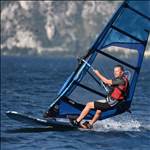
The version I used was the one in the pic in this thread with the gopro housing, green holder with an elastic strap on my left arm.
The wind was in the low 3 beaufort and the speed was not more then 7 km. Hey it works.
11 sats on the display.
I had to wait to later that day the wind increased and planing was possible. Yeah reached 20+ km.
Speed easily visible even without glasses.
Wind increased, the gusts got heavier and the speed increased too.
Could reach a 43 km as top speed.
Reading quickly the txt file at home confirmed what I saw while surfing.
I am a happy man.
Thank you Jan for providing this elegant tool.
Paco
What a great project this is. I have finished building my gps logger and everything seems to function well. Unfortunately, when using it several times I have had the following message:
'No GPS frames for more than 10s'.
The display indicates contact with 26 satellites.
This occurs after more than half an hour of use.
I have to switch the GPS logger off and on again to make it work again.
I am using the BE-280 GPS receiver and have set the settings to 3 GNSS (GPS + GLONAS + GALILEO) @ 5Hz sample rate
Does anyone have an idea what this could be due to?
It seems to me like a hardware issue. Or the GPS module stops sending correct ubx frames, or the wiring between GPS-EPS is failing, or the T5 ESP board itselfs is failing. Did you ever had salt water leakage ?
After this message, a reboot is always necessary.
Greetings, Jan.
Select to expand quoterp6conrad said..
It seems to me like a hardware issue. Or the GPS module stops sending correct ubx frames, or the wiring between GPS-EPS is failing, or the T5 ESP board itselfs is failing. Did you ever had salt water leakage ?
After this message, a reboot is always necessary.
Greetings, Jan.
I've only used it a couple of times and haven't had it open.
But I will see if water got in, and I will check the wiring. (I haven't used it in salt water).
Thanks for the reply, I now know what to look for.
Select to expand quoteJEB4workaround said..
What a great project this is. I have finished building my gps logger and everything seems to function well. Unfortunately, when using it several times I have had the following message:
'No GPS frames for more than 10s'.
The display indicates contact with 26 satellites.
This occurs after more than half an hour of use.
I have to switch the GPS logger off and on again to make it work again.
I am using the BE-280 GPS receiver and have set the settings to 3 GNSS (GPS + GLONAS + GALILEO) @ 5Hz sample rate
Does anyone have an idea what this could be due to?
What battery do you use?
if the battery is weak, even for a while this message can pop up.
Select to expand quoteBigBoss said..JEB4workaround said..
What a great project this is. I have finished building my gps logger and everything seems to function well. Unfortunately, when using it several times I have had the following message:
'No GPS frames for more than 10s'.
The display indicates contact with 26 satellites.
This occurs after more than half an hour of use.
I have to switch the GPS logger off and on again to make it work again.
I am using the BE-280 GPS receiver and have set the settings to 3 GNSS (GPS + GLONAS + GALILEO) @ 5Hz sample rate
Does anyone have an idea what this could be due to?
What battery do you use?
if the battery is weak, even for a while this message can pop up.
Good to know
I have have a 3.7V 2500Mah 103450 Lipo Polymeer Lithium installed and its fully loaded.
Select to expand quoteBigBoss said..JEB4workaround said..
What a great project this is. I have finished building my gps logger and everything seems to function well. Unfortunately, when using it several times I have had the following message:
'No GPS frames for more than 10s'.
The display indicates contact with 26 satellites.
This occurs after more than half an hour of use.
I have to switch the GPS logger off and on again to make it work again.
I am using the BE-280 GPS receiver and have set the settings to 3 GNSS (GPS + GLONAS + GALILEO) @ 5Hz sample rate
Does anyone have an idea what this could be due to?
What battery do you use?
if the battery is weak, even for a while this message can pop up.
I think I will try another battery, to find out if this is the problem. Does anyone have an aliexpress URL for me of a battery that has been proven to work well? (It should fit in the 83x58x33mm housing)
Good day Jan, if I have blown the GPIO39 pin, can I reroute and use the GPIO36 pin instead and change the .213bn .cpp or .h code to use that pin? Or any other free pin?
Thanks, Paco
Select to expand quotePacoRaapNL said..
Good day Jan, if I have blown the GPIO39 pin, can I reroute and use the GPIO36 pin instead and change the .213bn .cpp or .h code to use that pin? Or any other free pin?
Thanks, Paco
GPIO 36 has no internal pullup, I advice to use GPIO12. I will compile a 213BN version with this pin activated and send you a .bin file.
Greetings, Jan.
Select to expand quoterp6conrad said..PacoRaapNL said..
Good day Jan, if I have blown the GPIO39 pin, can I reroute and use the GPIO36 pin instead and change the .213bn .cpp or .h code to use that pin? Or any other free pin?
Thanks, Paco
GPIO 36 has no internal pullup, I advice to use GPIO12. I will compile a 213BN version with this pin activated and send you a .bin file.
Greetings, Jan.
Thanks Jan, this works fine. I got 2 new boards.
One I got working but the second one when I added the switch got hot at the rear of the board.
So I think I did something wrong.
But with this reworked version I can use GPIO12 pin fine.Thanks for your quick assistance.
Paco