The original FangyFin was designed as a good all-rounder for use in shallow or weedy water. The performance is skewed toward providing strong lift and reliable handling, rather than a dedicated speed fin. So the next challenge for me was to design a FangyFin that has a lower drag,but retains some of the user-friendliness of the original.
The result is the FangyFin S. (codenamed Sid - after Sid Vicious) A FangyFin 22 was chosen as the test bed and my neighbours were treated to a sustained burst of angle grinding to get the foil thickness reduced. The first few versions of the fin were certainly slippery and exciting on the downhill and unsurprisingly, had a noticeable lack of bottom end power by comparison to the FF22.
The main problem was the handling was exactly as the project-name 'Sid Vicious' implies. This fin was a skinny and a rash piece of work and was guaranteed to have 'live fast and die young' feel. Overloading and aggressive feet easily induced spinouts, and overall, the fin was probably not much better than a Delta! The focus of the revisions was concentrated on making the fin more friendly.
The earlier Selig inspired foil was slowly modified and the maximum chord moved aft. I did a chunk of reading on the effect of the merge profile between the leading edge radius and foil body and as a result, the nose section of the leading edge is relatively blunt and rounded, but transitions to a fine edge after the first third. I modified the fillet slightly to copy the strut fillets used on the AC yachts.
Next job was to have Nebbian 3D print it for me. Because you should always be Batman, Nebs went for the black print, which has the effect always making the fin look awesome. You can see the extended fore and aft fillet sections. The fillet edge is thick to allow for a nice cast surface in this area. The final product will have the fillet polished to a very thin edge. I also modified the box section to allow for easier bolt hole placement.
Nebs printed the fin in two pieces.
And then expertly joined them together.
For those who already have an existing FF22, I can email the foil outlines so that you can make templates and grind it back to a Sid Vicious version. But please note: when cutting back an existing hollow FF22, there is a chance the foil skin will be perforated as the existing hollow is not always perfectly centred. I would suggest filling the hollow with expanding foam first and then be prepared to glass over any perforations that might occur.


Warning: Nerdy Bit follows. Go to Funny Images Thread Instead
www.seabreeze.com.au/forums/General-Discussion/Chat/The-Funny-Images-Thread?page=432#lastpost
I have been investigating the possibility of an interaction effect of the fillet and non-slender, rounded leading edge Delta wing, ie a FangyFin. With the increased scientific interest in UAV's, the planform of a Delta wing has been morphing and is no longer considered to be an exclusively highly swept wing. The research literature now describes as little as thirty-five degrees sweep/rake designs.
The ideal Delta has a sharp leading edge bevel to induce the primary vortex. Theoretically, this occurs at leading-edge and produces lift as the vortex travels back over the wing. It is at its most efficient at relatively high angles of attack, eg. 20 -30 degrees. The more intense the vortex, the greater the lift.
With a sharp leading edge, the vortex initiates near the root of the wing. Cropping the wing tip of Delta wings does not affect the vortex formation. Extending the trailing edge on a cropped Delta wing provides a greater surface area for the vortex to act upon before it loses coherence. Example, Delta XT fins.
At lower speeds and lower angles of attack, there is a degree of traditional airfoil 2D like circulation. Hence Delta fins with higher chord thickness are easier to use at lower speeds but are comparatively 'draggy'.
A rounded edge delta wing has several effects:
- reduces the primary vortex strength,
- delays the formation of the primary vortex,
- shifts the primary vortex origin out from the root toward the tip,
- increases the formation of a secondary(inner) vortex,
- creates a more stable primary and secondary vortex.
What follows are my educated guesses. I have no modelling or scientific analysis to add weight to my thoughts. Please do not view them as facts! I can provide the 3D CAD files should anyone wish to do a formal model analysis.
The FangyFin 22 Sid produces only moderate levels of low-speed lift due to the thinned 'low drag' foil shape. At higher speeds, the spanwise flow begins to dominate the fore aft-flows and the low-pressure area on the lifting surface begins to organise into a vortex structure and begins shifting toward the leading edge, and the fins behave more like a delta planform.
The stability of the fin is partly due to the stability of the flow from;
- initially, a foil shape that promotes laminar-like flow,
- at moderate speeds, the stable vortex generated by a rounded leading edge in the first third of the leading edge.
- the outer two-thirds leading edge transitions to a relatively sharp leading edge that is more traditionally associated with a delta wing and in turn promotes vortex formation. I think this might help account for the stability and retrievability of the fin with sudden increases in angle of attack/pitching in the chop, but I have no hard/modelled evidence to support this notion.
- at very low angles of attack, there is poor vortex formation, and this may account for a lack of 'feeling' from the fin when going too deep off the wind.
To summarise: The fillet provides less turbulence at the root. The rounded leading edge in the first span-wise third of the leading edge moves the vortex initiation toward the wing tip. I think the combined effect is to stop the primary vortex interacting with the pressure wave turbulence resulting from the board/fin junction and therefore reducing the likelihood of ventilation.
All I need now is some weedy water to speed test the fin in and see whether all my thinking is bulldust or not.

Looks great Fangman! I was starting to wonder what had happened to that blank. Great to see that your team of magic elves were able to turn the plastic into metal.
Keen to hear how it goes.
Thanks Fellas. ![]() ^Powersloshin I will give it a whirl in some smooth and make sure it does not misbehave deep downhill and then get in touch if it's perfecto.
^Powersloshin I will give it a whirl in some smooth and make sure it does not misbehave deep downhill and then get in touch if it's perfecto.![]()
Hey Ross, did you have to do some re work ( cut out) to the back of the ATT to fit the FF on the WT ?
Select to expand quoteFNQBilly said..
Hey Ross, did you have to do some re work ( cut out) to the back of the ATT to fit the FF on the WT ?
Well spotted Billy! Yes, the extended trailing fillet on the FF22Sid does overlap the ATT, whereas the standard fillet design does not. However, I generally don't have much flex on the dial when going for speed ( because the water is smooth), and so the amount of flex under the fillet overlap is imperceptible.
I did do the experiment and try the fin in chop with the ATT fully dialled out and flexing. There was no difference in fin behaviour that I could pick, that is, no increase in spin-out or loss of lift.
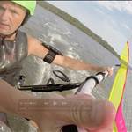
I have been trying to get a photo of the leading edge bluntness at the root, and transition to a fine edge at the wing tip.
It turns out it's hard to light the edge and on a highly polished surface evenly. Plus even with my f-stop at max it was hard to get the focus right. Hopefully, these images give a reasonable indication. ![]()


A question, forgive me if its dumb, obviously you have had the 3d prints made in order to make a (I presume sand box) mould to cast the aluminium into. Could you 3d print the moulds themselves and not use ali but carbon or something else (don't hate me Im just wondering!) OR could you straight out 3axis cnc the fins from G10 or even ali itself? Could you 3d print one of the carbon infused filaments?
Could you sell the 3d files to people to create their own versions ? Just ideas maybe dumb but just wondering?
Select to expand quotepeterowensbabs said..
A question, forgive me if its dumb, obviously you have had the 3d prints made in order to make a (I presume sand box) mould to cast the aluminium into. Could you 3d print the moulds themselves and not use ali but carbon or something else (don't hate me Im just wondering!) OR could you straight out 3axis cnc the fins from G10 or even ali itself? Could you 3d print one of the carbon infused filaments?
Could you sell the 3d files to people to create their own versions ? Just ideas maybe dumb but just wondering?
Any questions that give me a good excuse for not cleaning up the garage is immediately not a set of dumb questions at all! The short answers are yes, yes, yes, yes and yes.![]()
My original plan was to 3D print and use the fin straight off the printer.(print and play) I researched 3D materials etc and ended up collaborating with Prof M in het Panhuis at the Uni of Wollongong in trying to get a working printed fin. We tried Onyx and other types of University formulated special carbon blended print materials. The printed fin looked great, was super light, but simply wasn't strong enough. We eventually settled on a laser sintered titanium frame with the carbon printed over the top. The cost per unit was just about $5000, so needless to say it didn't get much further.
FF20 fresh out of the printer: The first attempt at a Print 'n Play fin. Material is ONYX which printed to an immediately nice surface finish, was under 400grams, but was too weak structurally. 
And this sort of set the trend. There are a lot of different ways to do the fin using current technologies, and I reckon I evaluated and got quotes for dozens of combinations, but the problem is always the cost per unit. Sending production offshore and having large production numbers will drastically reduce the cost per unit. However, I wanted to produce the fin in 100% in Australia and I don't ever expect to manufacture enough to make mass production viable. ( in fact, I don't ever expect to break even - but that's a whole different story)
Aluminium was chosen because it offered the best strength/surface hardness/cost ratio. Part of the original design criteria was to produce a tough fin that would last a lifetime of sailing in thick abrasive weed along with the occasional touch down on Mother Earth. So far the aluminium has done very well in what is a hostile environment for other materials. The SA boys have led me to believe that the aluminium is quite adept at taking on Razorfish as well.
I still want to have a direct print and play fin, but for the time being, the $ dictate that the old fashion cast aluminium by Fred in his little foundry is the best compromise. All the 3D files are available to anyone who wishes to experiment with the design/manufacture for free. ( They are covered with a Creative Commons licence that allows anyone to do what they like with them other than use them for commercial gain )
Ok interesting so Onyx is the "toughest" FDM material you could find I assume, in what way did it fail, too prone to abrasion, to soft for twist, or just too weak to have the required structural integrity . I must admit I was thinking more the SLM 3D printing method. We have had things made for shows (i work in film) with good results, however we were chasing cosmetics and fine detail not durability stiffness etc etc. What threw me was the cutting down and regrinding etc as that, then pretty much undoes all your hard design work on the computer with these very specific sections you have evolved so well. All very interesting. As for breaking even....crowd funding.....worked for Izzy Folau!
Select to expand quotepeterowensbabs said..
Ok interesting so Onyx is the "toughest" FDM material you could find I assume, in what way did it fail, too prone to abrasion, to soft for twist, or just too weak to have the required structural integrity . I must admit I was thinking more the SLM 3D printing method. We have had things made for shows (i work in film) with good results, however we were chasing cosmetics and fine detail not durability stiffness etc etc. What threw me was the cutting down and regrinding etc as that, then pretty much undoes all your hard design work on the computer with these very specific sections you have evolved so well. All very interesting. As for breaking even....crowd funding.....worked for Izzy Folau!
The toughest FDM was the Prof had his own special blend of herbs and spices ( and carbon ). I cant remember the numbers but it was a big improvement on Ultem and Onyx. The test was a 50N load applied to laterally to the fin. The base of the fin was held in a vice mounted horizontal and a 50kg weight to be applied. I don't recall the printed FF20 pictured even getting close. By comparison the aluminium FF20 has had 110kg load (me standing on it!) applied laterally and survived.
"....What threw me was the cutting down and regrinding etc as that, then pretty much undoes all your hard design work on the computer with these very specific sections you have evolved so well..." You are dead right! But on the up side I am way better on the angle grinder than I used to be ![]()
As for funding - the project was to create a fin so everyone could enjoy a sail in the heavy weed/shallows here. I still get a buzz just seeing sailors come in with a massive grin after their first go in the weedy smooth - that's the payday for me!
Select to expand quotefangman said..
As for funding - the project was to create a fin so everyone could enjoy a sail in the heavy weed/shallows here. I still get a buzz just seeing sailors come in with a massive grin after their first go in the weedy smooth - that's the payday for me!
Top Shelf, Legendary Ethics there Fangman. ![]()
Select to expand quoteolskool said..fangman said..
As for funding - the project was to create a fin so everyone could enjoy a sail in the heavy weed/shallows here. I still get a buzz just seeing sailors come in with a massive grin after their first go in the weedy smooth - that's the payday for me!
Top Shelf, Legendary Ethics there Fangman. ![]()
Not sure about that but Thank you all the same olskool. Smiles on Dials ![]()
I have looked into onyx as well, at this point cost prohibitive unless you invest in a printer yourself. Also limited to 320mm length. i was going to make samples but too expensive.
Select to expand quotefangman said..peterowensbabs said..
Ok interesting so Onyx is the "toughest" FDM material you could find I assume, in what way did it fail, too prone to abrasion, to soft for twist, or just too weak to have the required structural integrity . I must admit I was thinking more the SLM 3D printing method. We have had things made for shows (i work in film) with good results, however we were chasing cosmetics and fine detail not durability stiffness etc etc. What threw me was the cutting down and regrinding etc as that, then pretty much undoes all your hard design work on the computer with these very specific sections you have evolved so well. All very interesting. As for breaking even....crowd funding.....worked for Izzy Folau!
The toughest FDM was the Prof had his own special blend of herbs and spices ( and carbon ). I cant remember the numbers but it was a big improvement on Ultem and Onyx. The test was a 50N load applied to laterally to the fin. The base of the fin was held in a vice mounted horizontal and a 50kg weight to be applied. I don't recall the printed FF20 pictured even getting close. By comparison the aluminium FF20 has had 110kg load (me standing on it!) applied laterally and survived.
"....What threw me was the cutting down and regrinding etc as that, then pretty much undoes all your hard design work on the computer with these very specific sections you have evolved so well..." You are dead right! But on the up side I am way better on the angle grinder than I used to be ![]()
As for funding - the project was to create a fin so everyone could enjoy a sail in the heavy weed/shallows here. I still get a buzz just seeing sailors come in with a massive grin after their first go in the weedy smooth - that's the payday for me!
I agree with others sentiments your ethics are fair and legendary. Thanks for indulging a curious old model makers questions. I look forward to acquiring some FF's down the track.
Pete.
Just a quick hijack of my own thread. The 3D print process the prof developed has been successful when applied to surfboards fins. Here are some of Marc's work and some more info in the links :
www.morgen-filament.de/category/marc-in-het-panhuis/
www.instagram.com/explore/tags/3dfinsuow/
panhuis.org/wp/

Ross, really looking forward to the comparison results so I can decide which 22 to get next ![]()
Thanks, Peter :-). So far this is what the comparison between the two looks like. I need to fill in the downhill behaviour box, and a few more sessions should allow me to identify Sid's vices and behavioural issues ![]()

The deadzone occurs on symmetric foils at very low angles of attack approaching zero. No lift is generated because the pressure difference between each side of the fin is too small to be effective. The fin lacks 'feel' at this point, almost like it is spun-out or a bit directionally 'wobbly', but as soon as the angle of attack increases, the lift is re-established and the fin 'grips' again.
>direct print and play fin, but for the time being, the $ dictate that the old fashion cast aluminium by Fred in his little foundry is the best compromis
understand rhe the casting benefits. What medium is Fred using for his Molds??
Petrobond gives a much smoother finish than green sand casting - just wondering
cheers Jeff
Select to expand quotejirvin4505 said..
>direct print and play fin, but for the time being, the $ dictate that the old fashion cast aluminium by Fred in his little foundry is the best compromis
understand rhe the casting benefits. What medium is Fred using for his Molds??
Petrobond gives a much smoother finish than green sand casting - just wondering
cheers Jeff
G'day Jeff :-) Fred is a Pattern Maker by trade so is I think is far more cluey than me on that side of things. Certainly, when he makes up the split patterns for me, the finish is pretty good. The cost per split pattern is approx $2000. So unless I think I will be making a lot of fins, getting a split pattern made is economically not worth it. Hence, for the first few FF22 Sids I will sand cast. If there is enough demand (and the fin isn't an anchor) I will then consider whether I can justify a split pattern. eg. On a DIY fin, the profit margin is $15-$20 and so you can see why I don't ever expect to break even! ![]()
![]()
FF24 Split patterns and core boxes

Select to expand quotefangman said..
Just a quick hijack of my own thread. The 3D print process the prof developed has been successful when applied to surfboards fins. Here are some of Marc's work and some more info in the links :
www.morgen-filament.de/category/marc-in-het-panhuis/
www.instagram.com/explore/tags/3dfinsuow/
panhuis.org/wp/
Those fins look suspiciously like CNC cut fins from compressed layered composite (like black G10 panel) Ross. I recon that photo is mislabeled. These ones look more like it ![]() :
:

That whole projects sounds like a great excuse for a research grant supported surf trip of a lifetime to me! I LIKE it! ![]()
Any plans to apply for a substantial grant to do your PhD in Fangy fin speed design? I volunteer as a tester. Of course we would have to go to Luderitz and Walvis Bay for valid testing. ![]() And probably a month or two at that desert oasis speed strip in North Africa!
And probably a month or two at that desert oasis speed strip in North Africa! ![]()
Hey Daffy, I will check with the Prof to confirm or deny... stay tuned.![]()
EDIT: I have been in touch with the Prof, his reply is as follows;
"...I confirm that all these fins are 3D printed!!!!!!
They were all printed on a Markforged printer used a nylon-carbon composite with a continuous carbon fibre laid through it to facilitate sufficient mechanical behaviour.
The mechanical flex behaviour of these fins is similar to commercial offerings from FCS and Futures.
Let me know if you need more information - happy to provide.
Professor Marc in het Panhuis FRSC
School of Chemistry and Molecular Bioscience
ARC Centre of Excellence for Electromaterials Science
Australian Institute for Innovative Materials
University of Wollongong..."
Now Daffy as penance you can write up the research grant proposal and applications for your most excellent idea for further research in the field ![]()
![]()
![]()
With all due respect, I am not convinced. Still looks very wrong to me. ![]() It would be nice to get an explanation of why the layered look that is exactly like a CNC cut fin, from a pressure laminated block of fibre cloth. Did he look at the correct picture? This one:
It would be nice to get an explanation of why the layered look that is exactly like a CNC cut fin, from a pressure laminated block of fibre cloth. Did he look at the correct picture? This one:

Fangman......I got some quotes on a sample thruster fin on a Markforged printer.. Onxy with carbon laid filaments..exactly what the prof is doing. Way too expensive!!!!
Love ya work.
Daffy....The 3d printer places thin layers of material on top of each other, so you will get steps between layers. That's why it looks like the same layers of glass in G10.
Oh, ye of little faith! ![]() Yep, that was the photo I sent him, and I have asked why the appearance is reminiscent of G10. (My guess is that it is due to the direction of printing but I am no expert) In the meantime, start writing-up that research grant proposal pronto.
Yep, that was the photo I sent him, and I have asked why the appearance is reminiscent of G10. (My guess is that it is due to the direction of printing but I am no expert) In the meantime, start writing-up that research grant proposal pronto.![]()
![]()
Select to expand quotejirvin4505 said..
>direct print and play fin, but for the time being, the $ dictate that the old fashion cast aluminium by Fred in his little foundry is the best compromis
understand rhe the casting benefits. What medium is Fred using for his Molds??
Petrobond gives a much smoother finish than green sand casting - just wondering
cheers Jeff
I just realised I didn't answer this question properly, sorry Jeff. I have been in touch with Fred at the foundry and when I haven't requested a set of patterns, he uses Fenotec which is a phenolic resin. Strictly one use only. I don't know how this compares with Petrobond for surface finish. The corporate blurb says it gives an ' improved finish' which I guess is vague enough to mean almost nothing.
www.vesuvius.com/content/dam/vesuvius/corporate/Our-solutions/our-solutions-master-english/foundry/iron-foundry/binders/brochures/fenotec-e.pdf.downloadasset.pdf